MV-9_Chapter 5. Teaching.pdf - 第109页
错误 ! 使用“开始” 选项卡将 제목 2 应用于要在此处显示的文字。 错误 ! 使用“开始”选项卡将 제목 2 应用 于要在此处显示的 文字。 . 5- 109 3) IC Bridge inspection teaching method - Conduct inspection of sh or t betw een l ead and lead for IC Bridge i nspect i on . ① Click <…
MV-9 User Manual
5-108
2) Teaching outline
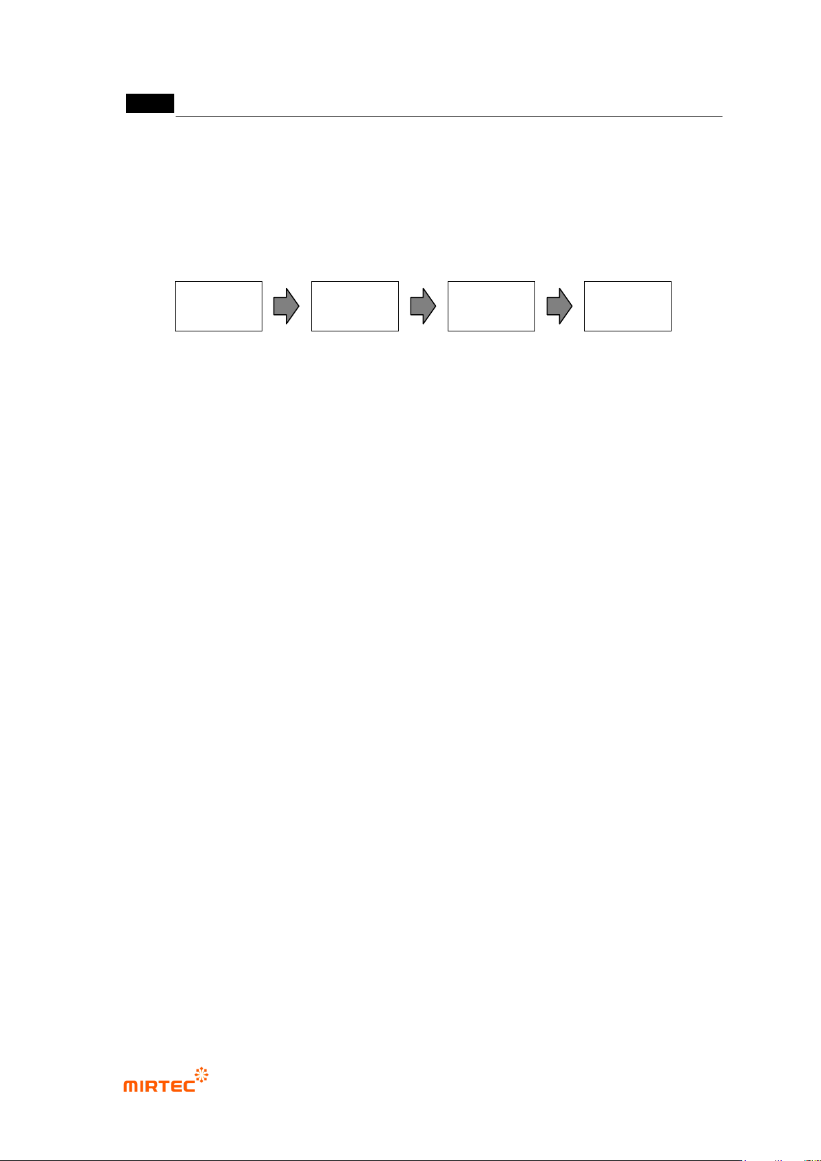
- Draw window and conduct 4 steps of setting for IC/Bridge inspection. Draw window to set
default parameter according to the image in the current screen. However, parameter
setting according to the following steps is recommended to increase inspection
performance.
[Figure 5-116 IC/Bridge inspection setting steps]
Bridge inspection area setting: lead separation tap
- Basically, this is to get gap area that is inspection area for bridge inspection. set light and
parameter for good lead separation of window area.
- In general, select R (red) for image type in horizontal + vertical light, and use an image that
applied high binarization value and noise removal.
Bridge inspection: Bridge inspection tap
- set light and parameter in which bridge can be defected well in gap area from lead
separation.
- In general, select B (blue) for image type in horizontal + vertical light, and use image with
low binarization value and no noise removal.
- In case of PCB with much amount of flux, remove flux by performing some noise removal.
Solder inspection area setting: lead tip tap
- Set parameter of lead tip tap to set area to detect solder defect. the most important
parameter on lead tip tap is to set to automatically achieve or user manually achieve using
the characteristic of which profile of end part appears low when profile is achieved through
lead image at position of lead end.
- In general, use image that completed auto binarization and some noise removal in vertical
light to detect automatically lead tip.
- Intersection area between lead tip position and lead area from lead separation will be
solder inspection area.
Solder inspection: solder amount inspection tap
- Conduct solder inspection for solder fillet area set in solder inspection area setting. Set
parameter for light and good/defect judgment suitable for solder inspection.
- In general, select B for image type in horizontal + vertical light. Sometimes horizontal –
vertical is selected. At this point, image type is automatically set to „L‟.
- Select use of lifted inspection and set parameter for good/defect judgment.
Bridge
inspection area
setting
Bridge
inspection
Solder
inspection area
setting
Solder
inspection
错误!使用“开始”选项卡将 제목 2 应用于要在此处显示的文字。错误!使用“开始”选项卡将 제목 2 应用
于要在此处显示的文字。 .
5-109
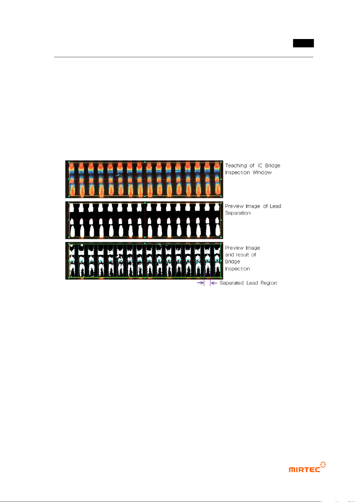
3) IC Bridge inspection teaching method
- Conduct inspection of short between lead and lead for IC Bridge inspection.
① Click <IC/Bridge inspection window> button among operating buttons.
② Draw inspection window in IC lead area to be inspected.
③ Select lead separation tap. Select light type and image type for good lead separation
checking preview. In case of noise around lead, use noise removal function. Check for good
lead separation through trial inspection.
④ Select Bridge inspection tap, and select proper light type and image type to detect foreign
material between lead checking preview.
[Figure 5-117 IC Bridge teaching]
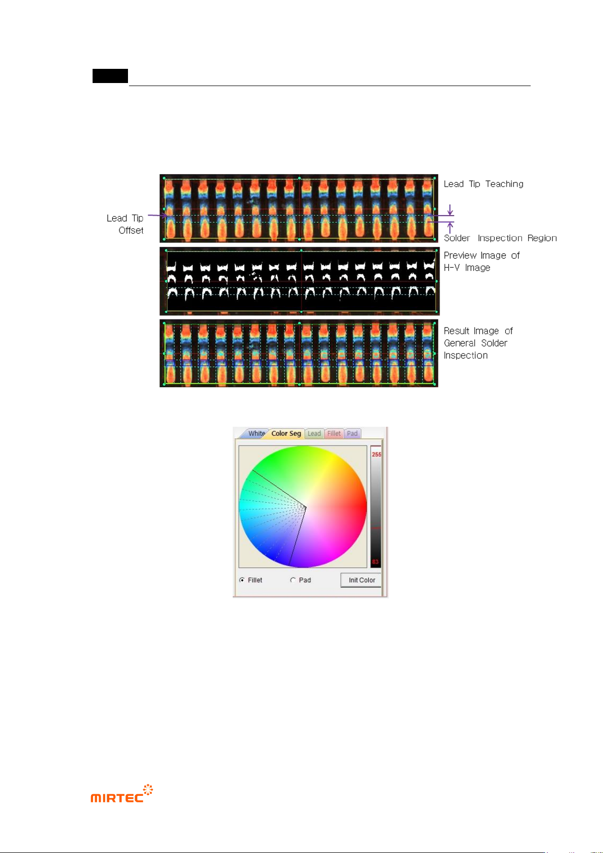
4) Solder amount inspection (general inspection) teaching method
- For solder amount inspection (general inspection), extract using binarization method that
used luminance information of inspection image or designation of color area for inspection
using color map adjustment, and conduct inspection by applying binarization method.
① Create inspection window using IC Bridge inspection teaching method.
② In case of conducting solder amount inspection, check at solder amount inspection over lead
separation tap.
③ Set lead tap position and solder inspection area on lead tip tap. Lead tip position can be
manually or automatically set.
④ Select solder amount inspection tap, select white tap of central part and enter normal criteria
to judge good/defect. In case of conducting lifted inspection, check lifted inspection, and
enter good/defect judgment criteria.
MV-9 User Manual
5-110
⑤ Basically, solder amount inspection will be conducted by using image luminance information.
However, in case of conducting solder amount inspection using color information of fillet that
used color map, check color binarization, select color tap, and adjust color map of fillet.
[Figure 5-118 IC Bridge – solder amount inspection (general inspection) teaching (lead tip manual
setting)]
[Figure 5-119 IC Bridge – solder amount inspection (general inspection) color map]
5) Solder amount inspection (advanced inspection) teaching method
- For higher defect detection rate than general inspection, solder amount inspection
(advanced inspection) divides inspection area into lead, fillet and pad to conduct more
precise inspection through inspection setting.
① To use solder amount inspection (advanced inspection), check at use color inspection on
lead tip tap, and check at use color inspection on solder amount inspection tap.