MV-9_Chapter 5. Teaching.pdf - 第231页
错误 ! 使用“开始” 选项卡将 제목 2 应用于要在此处显示的文字。 错误 ! 使用“开始”选项卡将 제목 2 应用 于要在此处显示的 文字。 . 5- 231 [Figure 5- 301 Module coordinate compensation stage 3 - move to position twisted wi ndow component posi t ion] ④ Com pensati on value is i…
MV-9 User Manual
5-230
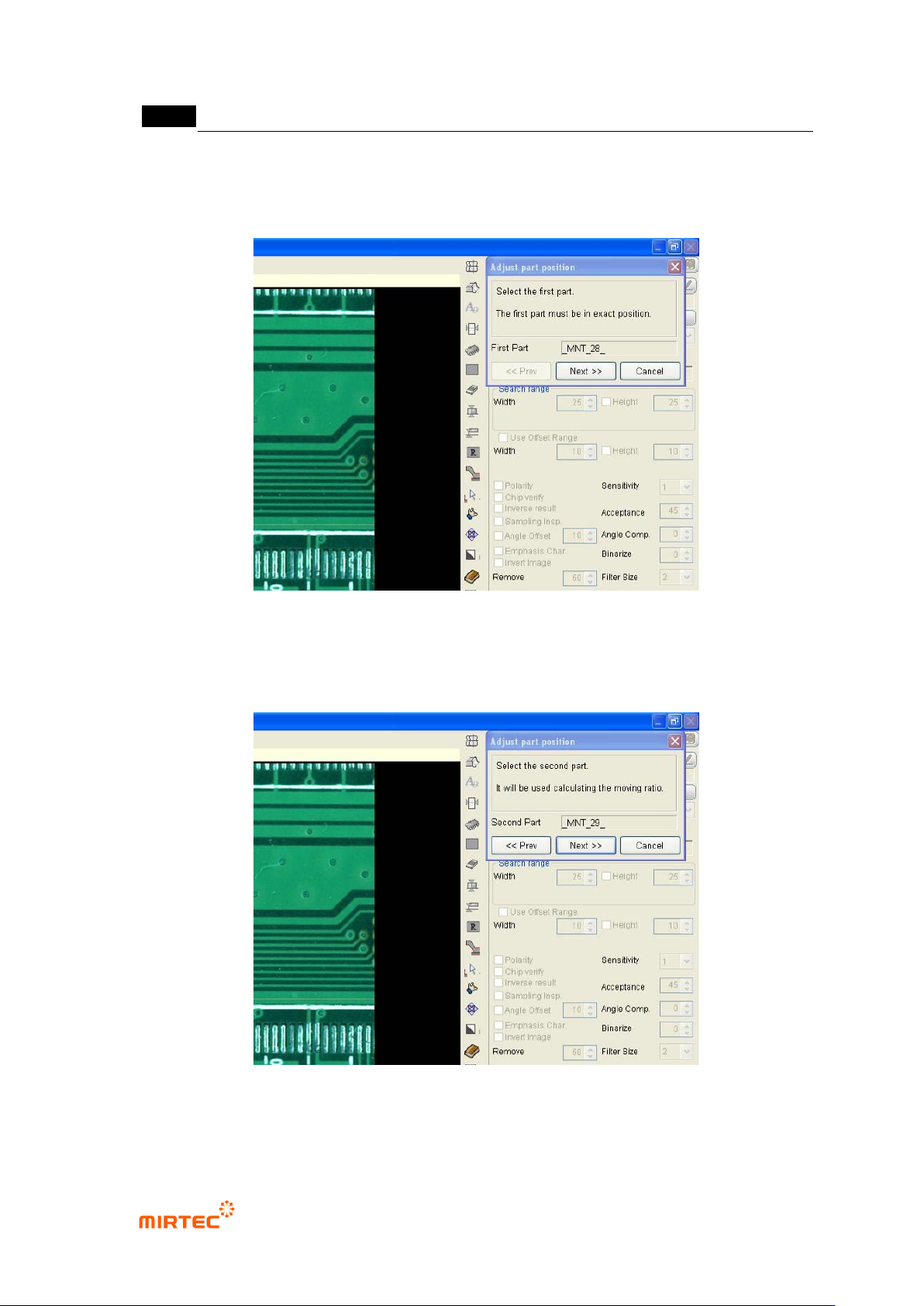
① Move robot to the frame in [Figure5-169]-(a) and select random 1 inspection window in
frame as show in the figure below. Click <Next> button in „component position
compensation‟ screen.
[Figure 5-299 Module coordinate compensation stage 1 - reference window selection]
② Move robot to the frame in [Figure5-169]-c, select random inspection window, and click
<Next> button in „component position compensation‟ screen.
[Figure 5-300 Module coordinate compensation stage 2 - selection of position twisted window]
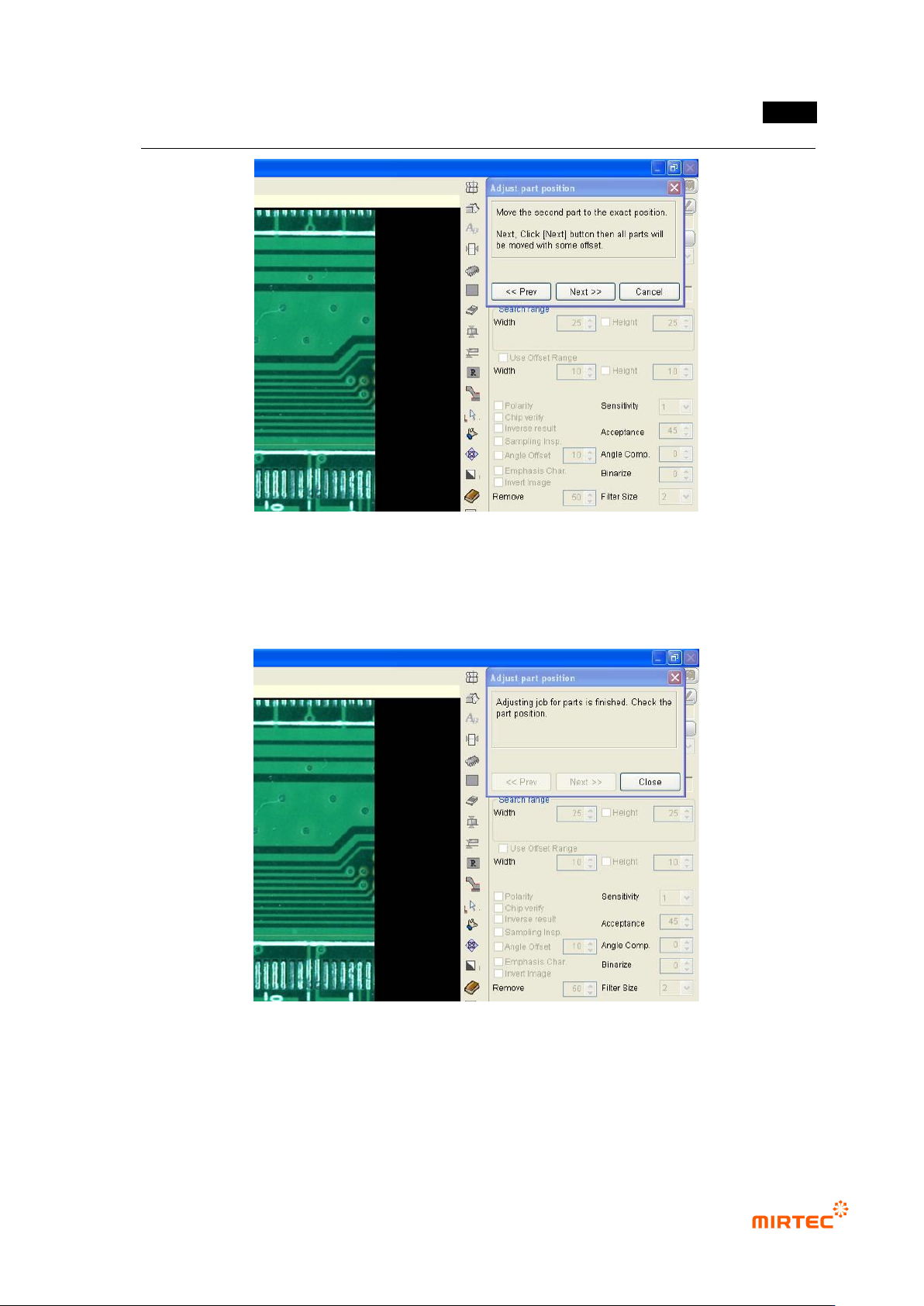
③ Move the selected inspection window to component position, and click <Next> button in
„component position compensation‟ screen.
错误!使用“开始”选项卡将 제목 2 应用于要在此处显示的文字。错误!使用“开始”选项卡将 제목 2 应用
于要在此处显示的文字。 .
5-231
[Figure 5-301 Module coordinate compensation stage 3 - move to position twisted window
component position]
④ Compensation value is internally calculated and the position of all inspection windows in
module will be compensated. Click <Close> button in „component position compensation‟
screen to finish module coordinate compensation.
[Figure 5-302 Completing module coordinate compensation]
Component position re-adjustment
Component position re-adjustment function is to re-adjust component position in each frame
using pattern matching method when component position in the currently selected module is
gradually twisted.
MV-9 User Manual
5-232
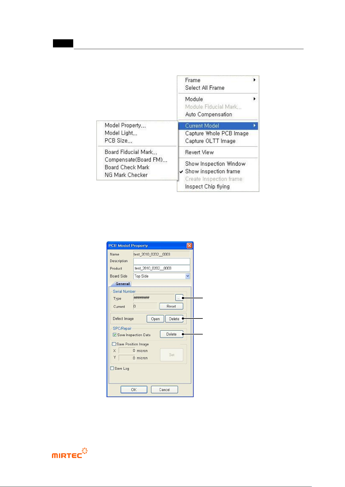
7) Current model related function
[Figure 5-303 current model menu]
This is used to edit information like light luminance value or NG marking use of currently opened
PCB model or change PCB size.
PCB model information ‘General’ tap
[Figure 5-304 PCB model information-general tap]
Serial No
Serial
Number
SPC & Repair
Improper Image
Folder