MV-9_Chapter 5. Teaching.pdf - 第276页
MV -9 Use r Manual 5- 276 Shift is created to invade the other p ad. ⑩ In case the LED i s l ong, there m a y be a rem arka ble difference in the y - Sh i f t value between the p osition of Center Points and the left/rig…
错误!使用“开始”选项卡将 제목 2 应用于要在此处显示的文字。错误!使用“开始”选项卡将 제목 2 应用
于要在此处显示的文字。 .
5-275
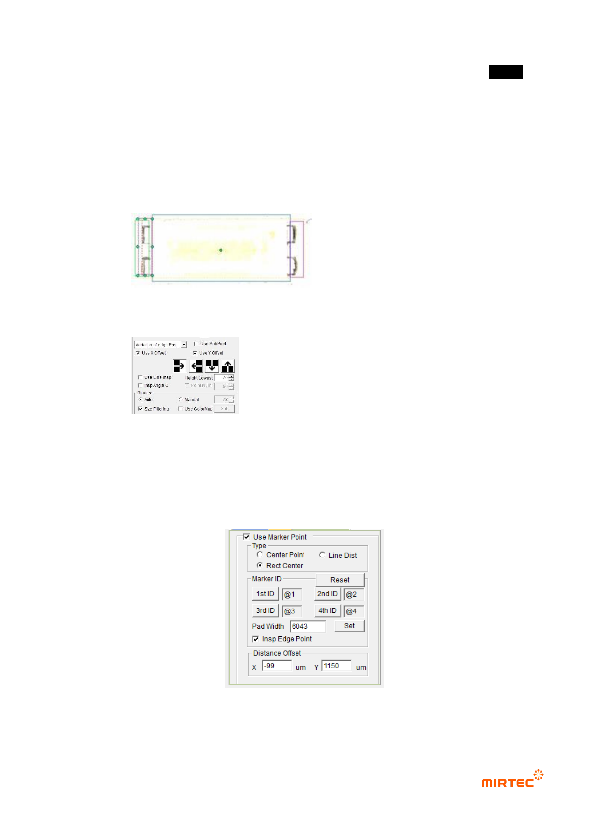
② After executing „Edit Parts‟ mode, set the parameters of each window.
③ Check the angle inspection for the windows drawn up/downward and do not check the
angle inspection for the windows drawn at both ends of the pad.
④ For the windows drawn at both ends of the pad, strengthen the vertical lighting by using
users‟ lighting in order to minimize the solder effect.
⑤ The parameter setting of the window at the ends of the pad is as follows:
⑥ Set the marker point in the order of top, bottom, left and right. Since the inspection is
made in the order of LED markers, it is impossible to conduct the inspection in case the
position of 1/2 and the position of 3/4 are changed to each other.
⑦ The parameters set for markers are as follows:
⑧ Input „Pad Width‟. If „Set‟ button is pressed, it is set automatically..
⑨ The Pad Width should be set to inspect the Shift on the basis of one pad in case LED
MV-9 User Manual
5-276
Shift is created to invade the other pad.
⑩ In case the LED is long, there may be a remarkable difference in the y-Shift value
between the position of Center Points and the left/right edge parts. In this case, it is
impossible to detect the poor quality with Center Point Shift. In order to compensate
for this, „Insp Edge Point‟ option is used.
- Before the use of Insp Edge Point : Inspect y Shift with the Center Point of
LED.
- After the use of Insp Edge Point : Inspect y-Shift with LED Max of both
edges.
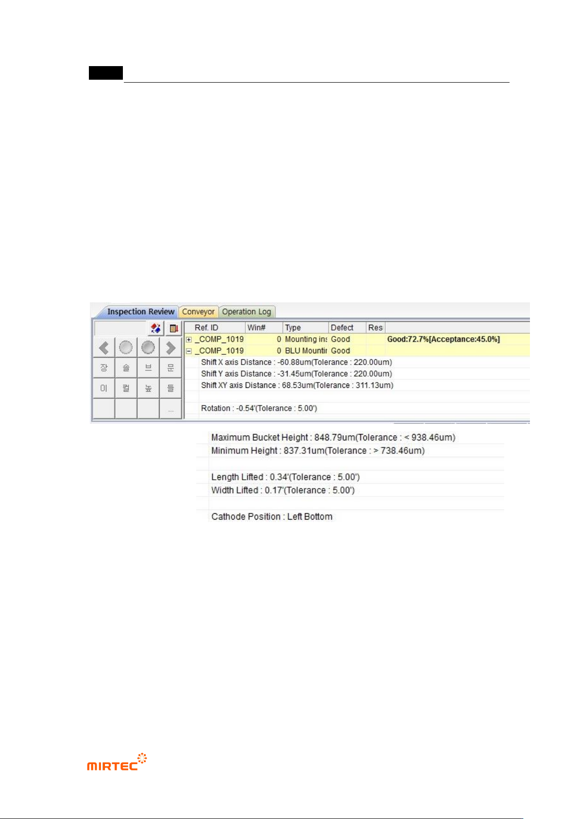
5.9.10 Inspection Results
50 Shift X axis Distance
- X axis distance between the reference Center Point and the current LED PKG
Center Point..
51 Shift Y axis Distance
- Y axis distance between the reference Center Point and the current LED PKG
Center Point..
52 Rotation
- Rotated angle of LED PKG.
53 Maximum Bucket Height
错误!使用“开始”选项卡将 제목 2 应用于要在此处显示的文字。错误!使用“开始”选项卡将 제목 2 应用
于要在此处显示的文字。 .
5-277
- The highest height out of the heights around four corners.
54 Maximum Height
- The lowest height out of the heights around four corners.
55 Length Lifted
- The lifted angle in the long-axis direction.
56 Width Lifted
- The lifted angle in the short-axis direction .
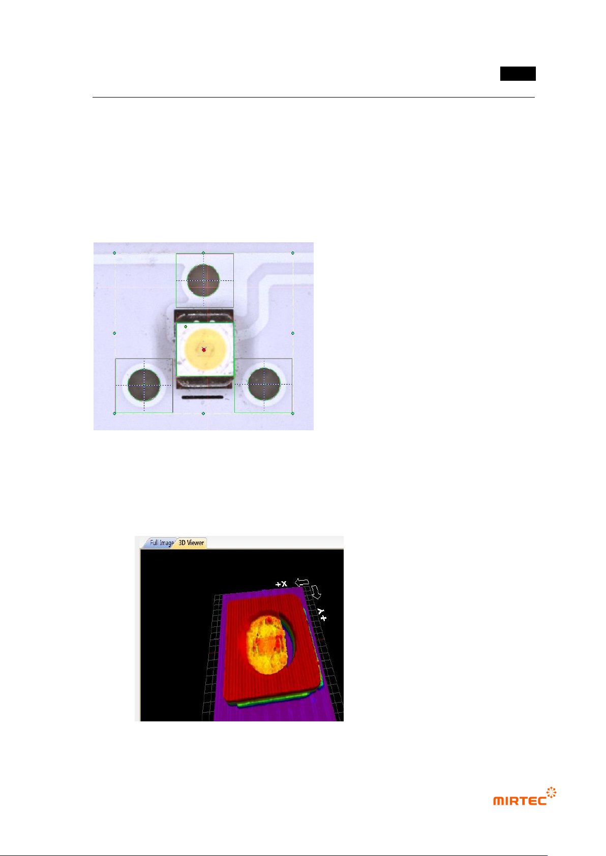
57 Center Point Marking
- The reference Center Point is marked with a red circle, and the Center Point of the
current LED PKG with blue X.
- 3D Model Marking
- The 3D Model measured by 3D Viewers is displayed..