MV-9_Chapter 5. Teaching.pdf - 第122页
MV -9 Use r Manual 5- 122 Use co lor in spec tion - Set this option to use color inspection. Check at „Use co l or inspect i on ‟ to activate it on solder amount inspection t ap. Solder inspe ction area setting - Th …
错误!使用“开始”选项卡将 제목 2 应用于要在此处显示的文字。错误!使用“开始”选项卡将 제목 2 应用
于要在此处显示的文字。 .
5-121
[Figure 5-133 Bridge defect example]
12) Lead tip parameter
- Check at solder amount inspection among default parameters to activate lead tip tap and
solder amount inspection tap.
- For lead tip position, set start point of fillet area for solder amount inspection. For setting
method of lead tip, there are manual setting to set lead tip position by user and auto
setting method at which program finds lead tip position.
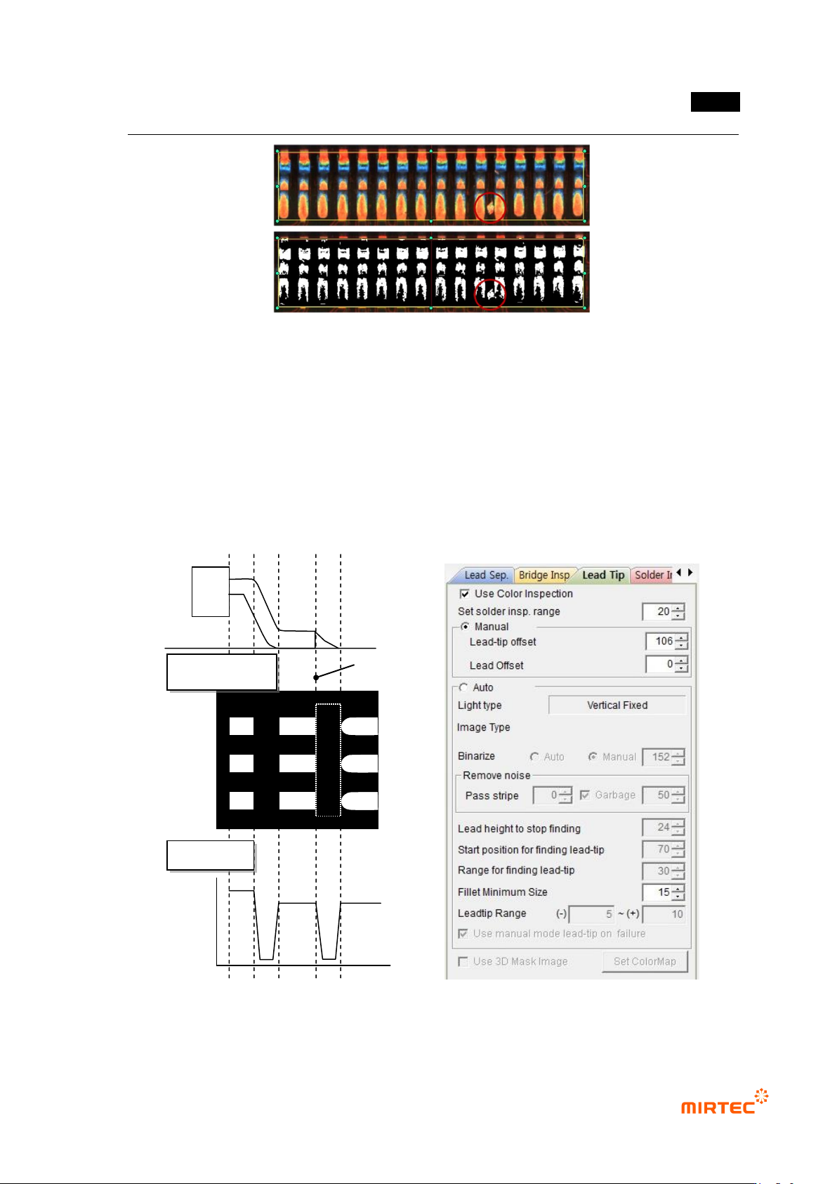
[Figure 5-134 lead image characteristic and lead tip parameter]
Lead tip position
Binarization image
Profile
MV-9 User Manual
5-122
Use color inspection
- Set this option to use color inspection. Check at „Use color inspection‟ to activate it on
solder amount inspection tap.
Solder inspection area setting
- This is manually set or set the degree of solder area from automatically found lead tip. real
solder area is common part of lead area found by lead separation and solder inspection
area set by lead tip offset value.
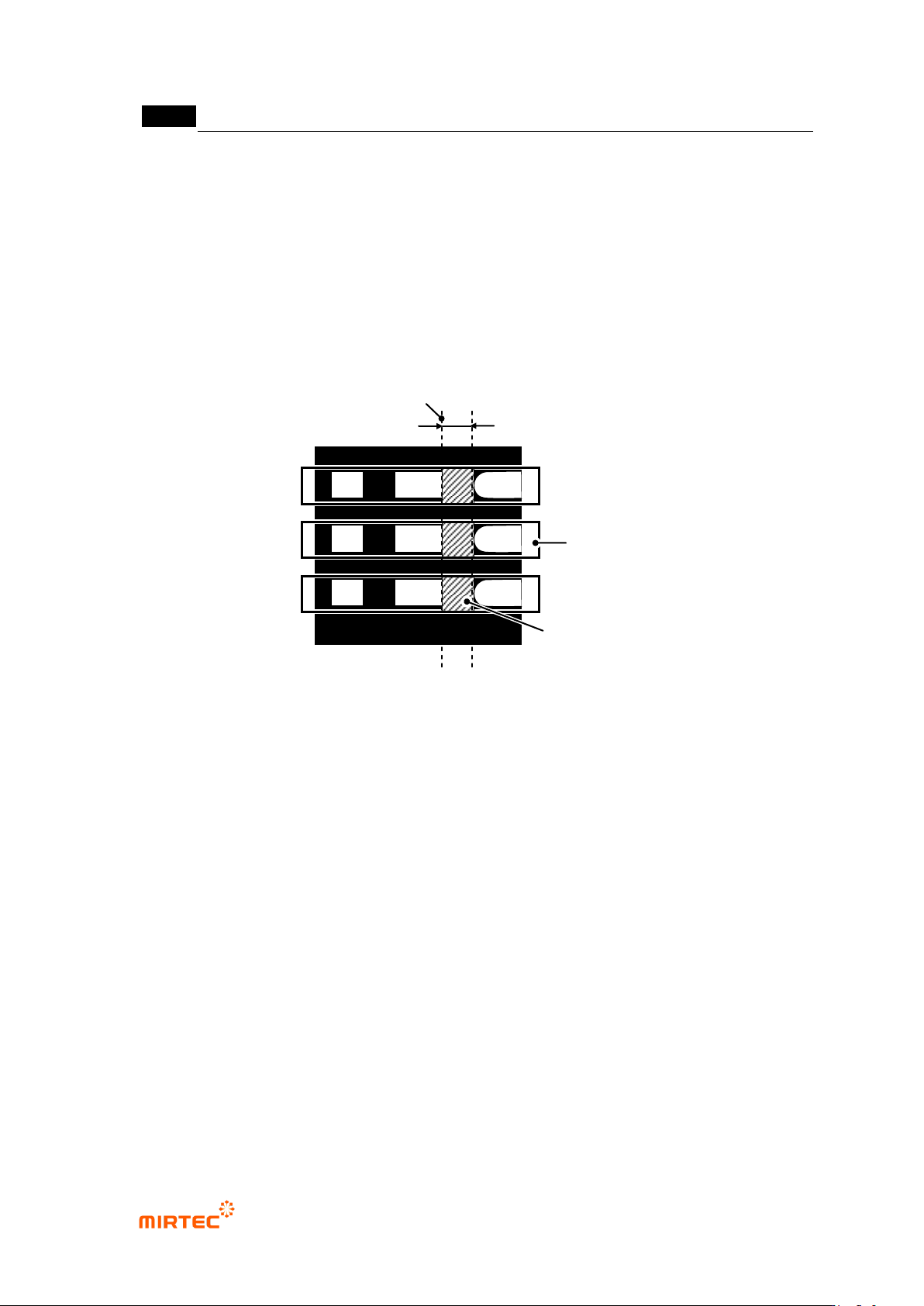
[Figure 5-135 lead tip and solder inspection area definition]
Manual
- Users manually designate position of lead tip. In general, use this option when position of
lead tip is not clearly separated and it is difficult to use auto search in binarization image.
- Lead tip offset: manually designate position of lead tip.
- Lead offset: used for solder amount inspection (advanced inspection). Designate start
position of lead area. Set to „0‟ for solder amount inspection (general inspection).
Auto
- In case of using lead tip auto search, adjust parameter to clearly divide position of lead tip.
- Since lead tip light is vertically fixed, adjust only binarization value and stripe width.
- Setting values in [Table 5-11] are recommended for setting of each item.
- When position of lead tip is not clearly divided after image adjustment, use manual setting
function to set lead tip.
Lead area
Lead tip set by auto or manual
Solder inspection area width
Solder inspection area

错误!使用“开始”选项卡将 제목 2 应用于要在此处显示的文字。错误!使用“开始”选项卡将 제목 2 应用
于要在此处显示的文字。 .
5-123
[Table 5-11 lead tip – auto setting value]
Item
Recommended setting value
light
vertical (Fixed)
binarization type
auto
stripe width
0 ~ 2
area
High (30 ~ 60)
Min lead width
- Lead tip of some lead is not completely separated in binarization image and connected. At
this point, set min lead width to find lead tip by not distinguishing low width value lower
than setting value from lead and there is little connection shape.
- width value to be set uses a little larger value than the value width of connection shape.
(Initial value is 50 %.)
[Figure 5-136 lead tip start point min lead width]
Search start position
- Set position to start lead tip search. Set shoulder part of lead and position between lead
tips and start program search from this position to lead tip position during inspection.
(search direction: lead toward package → lead end)
[Figure 5-137 lead tip inspection position]
Search range
- Activated when color inspection is checked. set search range of lead tip auto search.
Search start position
Lead tip position
Min lead width of start point of lead tip