MV-9_Chapter 5. Teaching.pdf - 第62页
MV -9 Use r Manual 5- 62 - Rect region (r e d r ectan gle in sold e ring i nspect io n ar ea ) In case o f pin type , create it about 60% of p ad size , s quare or rectangle, and correctly locate it at pad center as c …
错误!使用“开始”选项卡将 제목 2 应用于要在此处显示的文字。错误!使用“开始”选项卡将 제목 2 应用
于要在此处显示的文字。 .
5-61
Adjusting color map
- Since each of RGB will be independently adjusted in color map (center position, angle),
overlapping is possible.
- To detect defect of excessive solder characteristic on small pad below 3mm of diameter,
included in red area to 90 degree in green area. (Minimize it because green area is not
used.)
- Map adjustment using defect sample of excessive solder characteristic is the most
effective method.
- Important adjustment item to judge good/defect of sample within good/defect judgment
boundary.
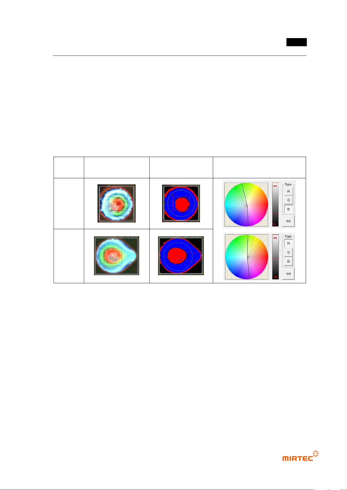
Component
type
Color image
Preview image
Color map setting status
pin type
lead type
[Figure 5-65 Example of color map adjustment using excessive solder characteristic defect]
Inspection area setting
- Circle region (green circle in soldering inspection area)
Exterior part has not big influence to good/defect judgment during real inspection, and
the area has high occurrence rate of false defect due to flux and others. Hence,
diameter of about 80% of real pad size is recommended.
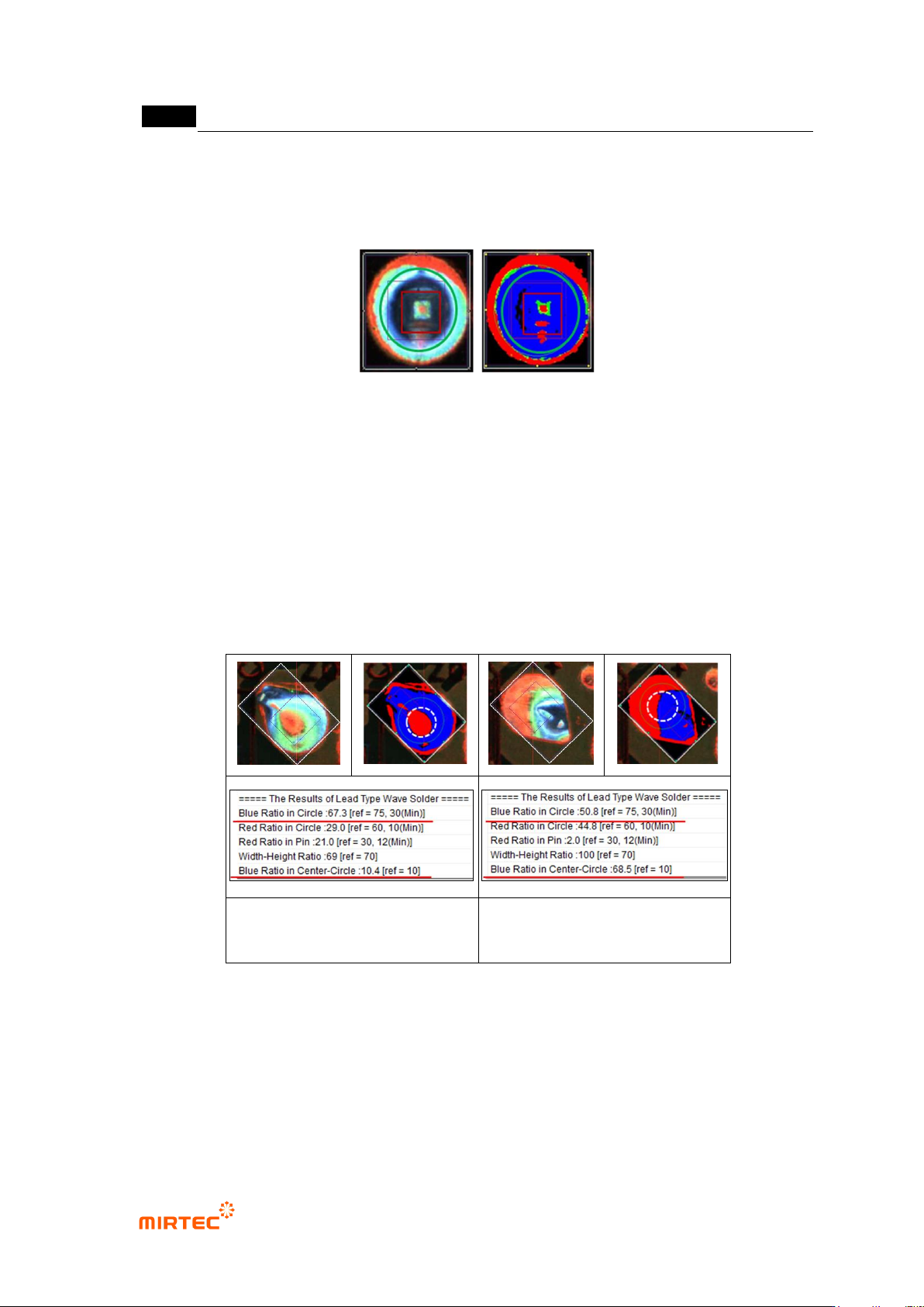
Especially, in case of pin type with big diameter, pad exterior part appears in read as
shown in the figure below, and it will be excluded from inspection area.
Since position compensation is not conducted for center position of circle region using
mounting inspection, correctly locate it at pad center as close as possible.
Blue ratio and red ratio will be changed by the size of circle area. Hence, this is an
important adjustment item to judge defect as normal or normal as defect within
good/defect judgment boundary.
MV-9 User Manual
5-62
- Rect region (red rectangle in soldering inspection area)
In case of pin type, create it about 60% of pad size, square or rectangle, and correctly
locate it at pad center as close as possible.
[Figure 5-66 Example of inspection area setting]
Center Circle region
- This region is same with the center of green circle, and defined as circle with half of green
circle diameter. This is used to check defect of excessive solder characteristic, and only
blue ratio will be calculated.
- As shown in [figure5-84], blue ratio of the left lead type is higher than that of right in green
circle. However, red ratio is higher than that of left lead type in white dotted line circle. This
is one of defects of excessive solder characteristic defect or defect with small lead amount.
Excessive solder characteristic
defect image
Normal image
[Figure 5-67 Setting example of Center Circle Region]
错误!使用“开始”选项卡将 제목 2 应用于要在此处显示的文字。错误!使用“开始”选项卡将 제목 2 应用
于要在此处显示的文字。 .
5-63
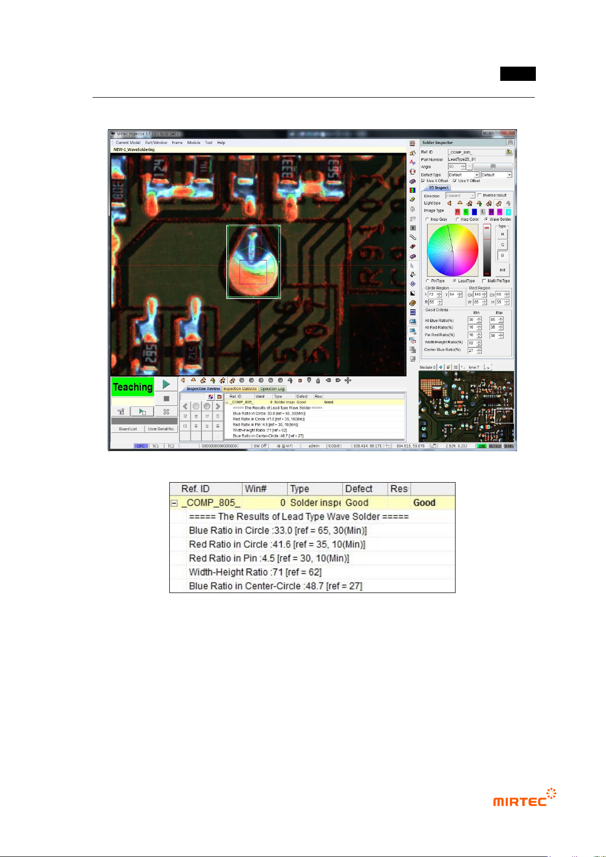
6) Inspection result in status screen
[Figure 5-68 Inspection result in status screen]