MV-9_Chapter 5. Teaching.pdf - 第200页
MV -9 Use r Manual 5- 200 [Figure 5- 248 Polarity inspection setting and preview image] [Figure 5- 249 Polarity inspection resul t] ④ Reference point (m ark ) teaching and setting - Use center position of circ le referen…
错误!使用“开始”选项卡将 제목 2 应用于要在此处显示的文字。错误!使用“开始”选项卡将 제목 2 应用
于要在此处显示的文字。 .
5-199
[Figure 5-246 Foreign material inspection result]
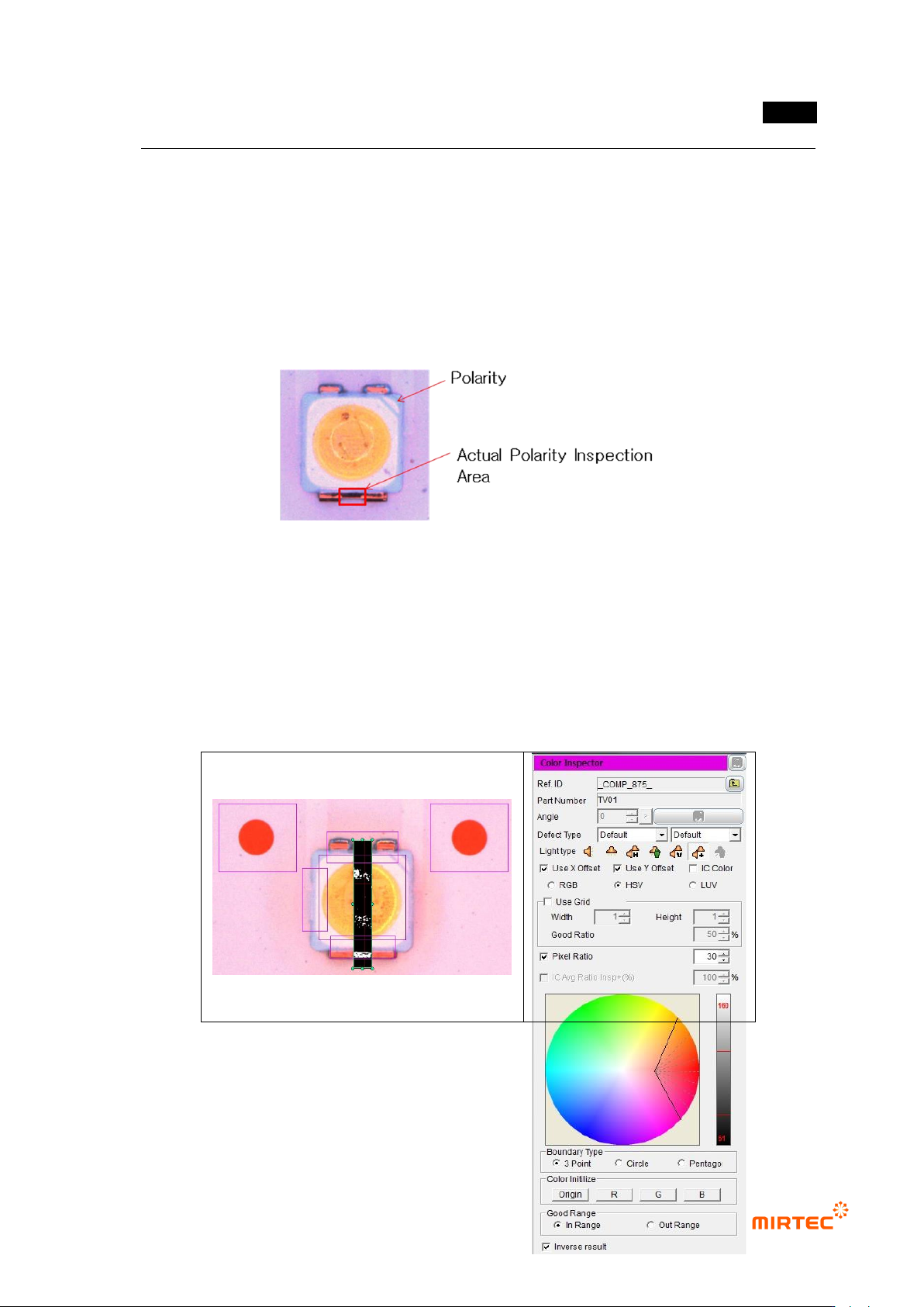
③ Teaching and setting Polarity inspection (color inspection)
- Polarity inspection is to detect mounted polarity of LED package, judge whether polarity
exists or not. In general, TV has a polarity mark (so called chamfering) on one corner of
package. However, since detection status differs from package, detect area difference
between LED electrodes using color inspection algorithm.
[Figure 5-247 Polarity inspection area]
- Conduct Polarity inspection through inspection for area between electrode and electrode
using color inspection window.
- Select HSV for color coordinator, and select pixel ratio.
- Adjust color map for electrode separation. If white pixel appears in area that completed
teaching, it is LED Polarity. Hence, check at “judge defect as normal”.
MV-9 User Manual
5-200
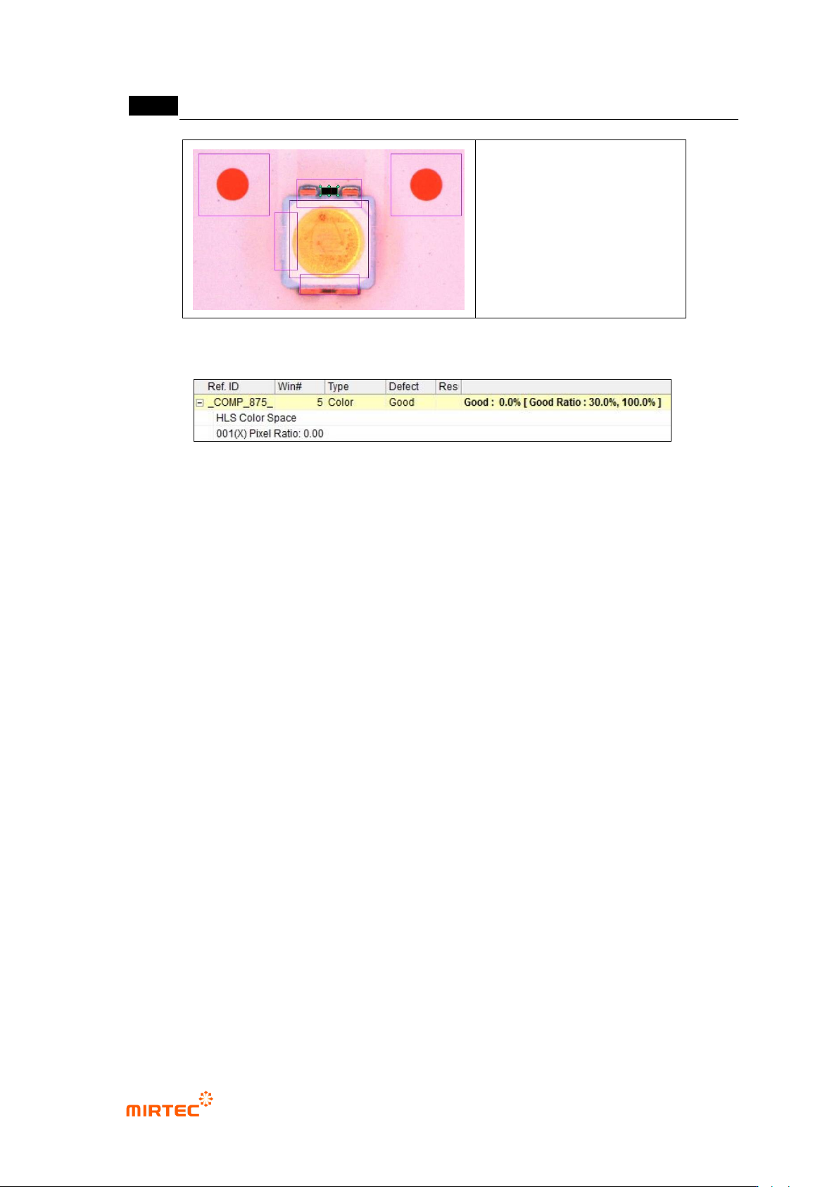
[Figure 5-248 Polarity inspection setting and preview image]
[Figure 5-249 Polarity inspection result]
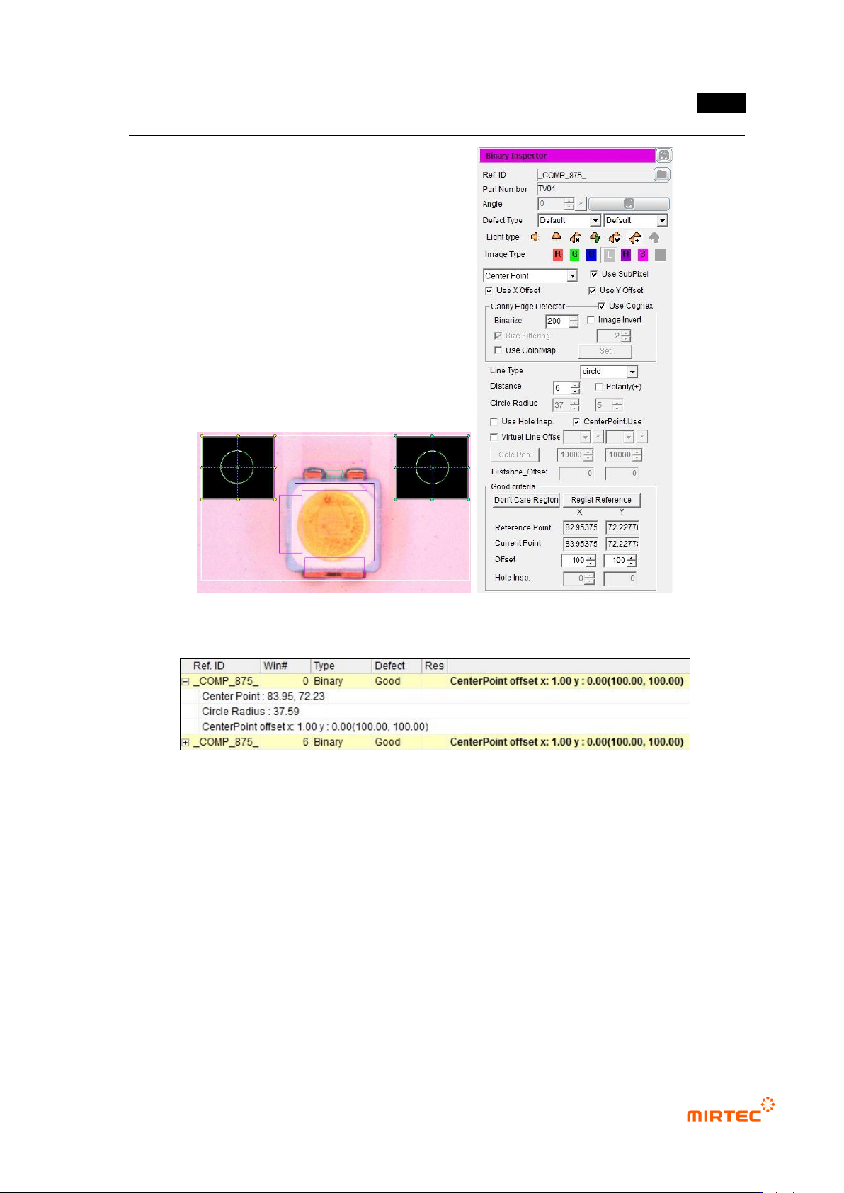
④ Reference point (mark) teaching and setting
- Use center position of circle reference point to inspect X/Y-shift of LED package.
- Create binary inspection window to detect center position of reference point, and select
component center search. select circle or center of gravity (center of gravity) for figure type.
- Check at „Use Subpixel‟. If Cognex license key is installed, check at „use Cognex‟.
- Select „preview‟, and adjust binarization for proper separation of edge of reference point
through color map-setting.
- Conduct trial inspection to display center position of reference point at the current central
point in inspection window. After normally calculating center, click „Register reference
central point‟.
- Set tolerance range as big as possible. reference point is used as criteria to inspect X/Y-
shift of LED package for BLU inspection. Hence, tolerance range is meaningless.
错误!使用“开始”选项卡将 제목 2 应用于要在此处显示的文字。错误!使用“开始”选项卡将 제목 2 应用
于要在此处显示的文字。 .
5-201
[Figure 5-250 Center of binary inspection-component search inspection setting and preview image]
[Figure 5-251 center of binary inspection-component search result]
⑤ Teaching and setting for X-shift inspection
- Measurement principle
Straight line 1 that links center of reference point 1 and reference point 2.
Create normal (straight line 2) of straight line 1 based on central point of reference
point 1.
Calculate vertical distance from straight line 2 using x coordinates of extracted
edge, and this calculated value is x-shift measurement value.