MV-9_Chapter 5. Teaching.pdf - 第111页
错误 ! 使用“开始” 选项卡将 제목 2 应用于要在此处显示的文字。 错误 ! 使用“开始”选项卡将 제목 2 应用 于要在此处显示的 文字。 . 5- 111 ② S el ect „ manual ‟ on lead tap , and set lead tip of fset to be sam e with solder am ount i nspection (general inspection). ③ Select „a…
MV-9 User Manual
5-110
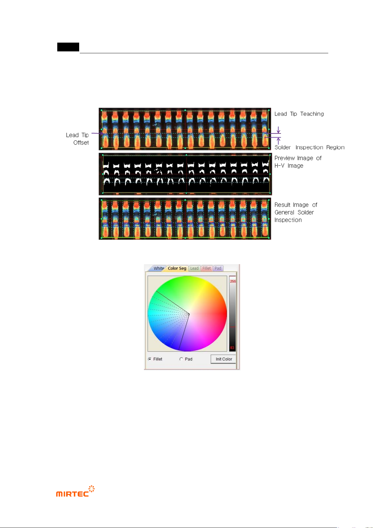
⑤ Basically, solder amount inspection will be conducted by using image luminance information.
However, in case of conducting solder amount inspection using color information of fillet that
used color map, check color binarization, select color tap, and adjust color map of fillet.
[Figure 5-118 IC Bridge – solder amount inspection (general inspection) teaching (lead tip manual
setting)]
[Figure 5-119 IC Bridge – solder amount inspection (general inspection) color map]
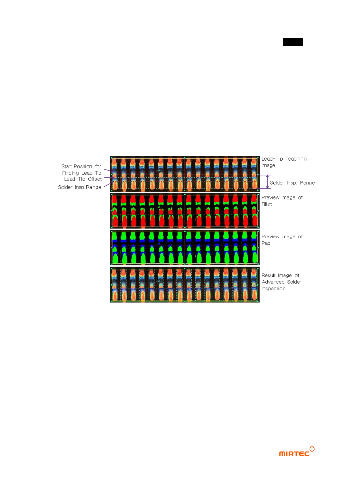
5) Solder amount inspection (advanced inspection) teaching method
- For higher defect detection rate than general inspection, solder amount inspection
(advanced inspection) divides inspection area into lead, fillet and pad to conduct more
precise inspection through inspection setting.
① To use solder amount inspection (advanced inspection), check at use color inspection on
lead tip tap, and check at use color inspection on solder amount inspection tap.
错误!使用“开始”选项卡将 제목 2 应用于要在此处显示的文字。错误!使用“开始”选项卡将 제목 2 应用
于要在此处显示的文字。 .
5-111
② Select „manual‟ on lead tap, and set lead tip offset to be same with solder amount inspection
(general inspection).
③ Select „auto‟ on lead tap, and set solder inspection area setting, search start position, search
range, min fillet size and lead tip range.
④ Check at „Use manual lead tip‟ if auto lead tip search fails
⑤ Select lead tap, and check at „Use lead inspection‟ and set inspection criteria.
⑥ Select fillet tap, and set binarization and normal criteria.
⑦ Select pad tap, and set binarization and normal criteria. Not to use pad inspection, check at
„Ignore pad area inspection‟.
[Figure 5-120 IC Bridge – solder amount inspection (advanced inspection) teaching (lead tip auto
setting)]
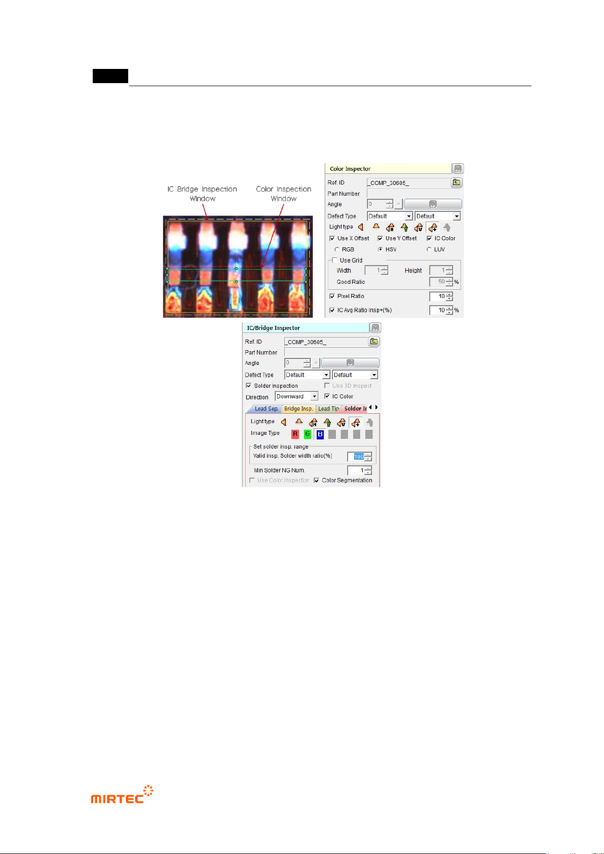
6) IC color teaching method
- In case of occurrence of lifted lead, IC color inspection detects lifted lead defect using the
characteristic of which color of lead shoulder or lead tip is different from normal. This
method detects defect through color inspection for intersection area between lead
separation area and color inspection window area in IC Bridge inspection window.
① Draw inspection window in IC Bridge inspection teaching method.
② Draw color inspection window in area for color inspection.
③ Select both of IC Bridge inspection window and color inspection window, and select „Group
component‟ in popup menu (click the right button of a mouse).
MV-9 User Manual
5-112
④ Check at „IC color‟ in IC Bridge inspection, and check at IC color in color inspection.
⑤ Check at pixel ratio in color inspection. For inspection of comparison with average value,
check at IC average ratio inspection+ (%).
[Figure 5-121 IC color inspection teaching]
7) Example of representative component teaching
Drawing IC Bridge window
Draw window to include all areas in which Bridge can occur.
If the end of window includes package, bridge defect can occur by package area. Hence,
draw from position a little away from package to lead end.
Compensation using compensation window
Inspection position can be out of actual inspection position a little bit due to robot error or
others if real robot is moved during. Hence, add compensation window and group them
into a component for bridge inspection. compensation window finds actual position of
Bridge for compensation of bridge window to increase inspection reliability.
In general, set bridge compensation window at which lead starts at package and use
search range at lead direction for search range in compensation window and use small