MV-9_Chapter 5. Teaching.pdf - 第165页
错误 ! 使用“开始” 选项卡将 제목 2 应用于要在此处显示的文字。 错误 ! 使用“开始”选项卡将 제목 2 应用 于要在此处显示的 文字。 . 5- 165 Col or i nput param ete r This is to input, add or delete color inform ation of band that is current l y selected. B and No Select ban…
MV-9 User Manual
5-164
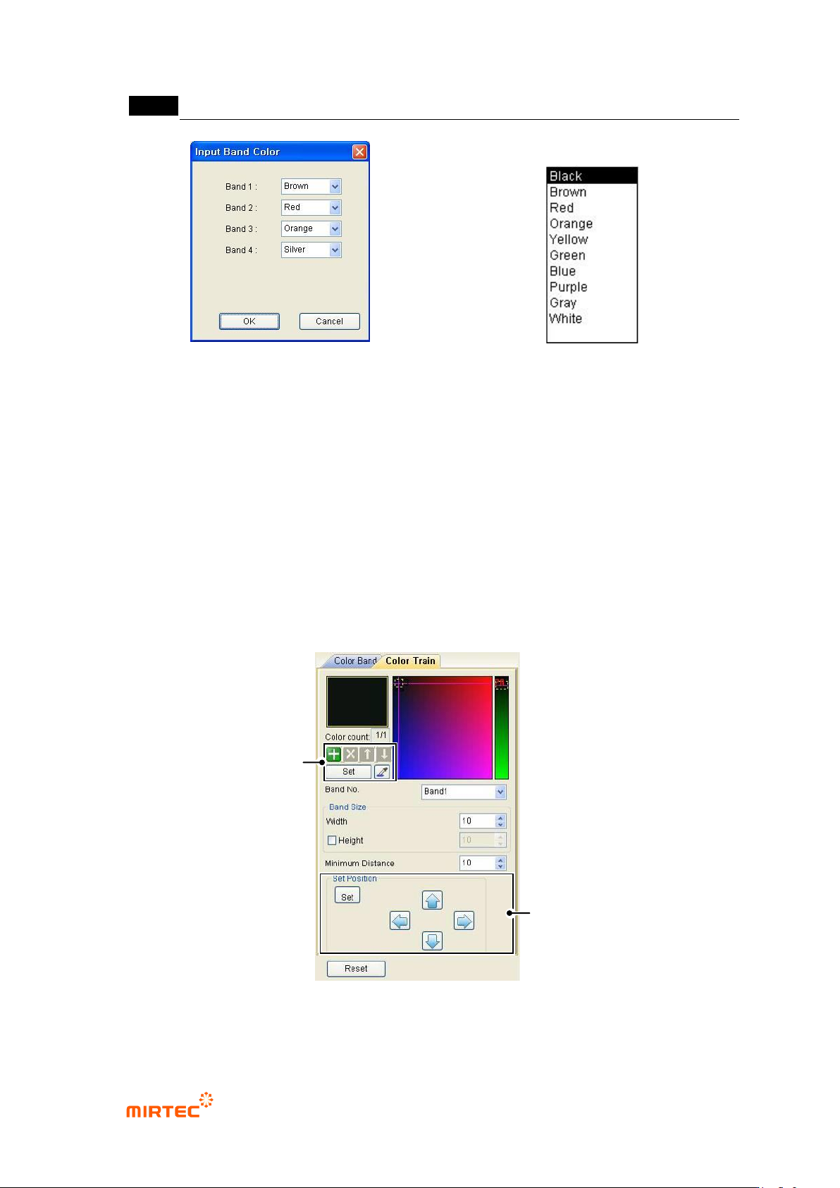
[Figure 5-197 band color input screen]
[Figure 5-198 band color list]
Tolerance
Enter resistance tolerance.
Tolerance ignore
Important parameter for real resistance is resistance value. If the importance of tolerance
is low, and conduct inspection after excluding tolerance.
Number of resistance color band
Set the number of resistance color band.
Body color
Enter body color of resistance. If body color of resistance is same with series of color with
color band, set this option to prevent wrong recognition of color band by body color.
Color input
[Figure 5-199 Color input setting screen]
Color Input
Window
Location Input
Window
错误!使用“开始”选项卡将 제목 2 应用于要在此处显示的文字。错误!使用“开始”选项卡将 제목 2 应用
于要在此处显示的文字。 .
5-165
Color input parameter
This is to input, add or delete color information of band that is currently selected.
Band No
Select band No.
Band size (width/height)
Judge size of area for band color inspection.
Min distance
Min distance means relative distance to target color from each reference color. This is to
distinguish normal condition during inspection.
Position input parameter
Set position of currently selected band. Click <Set> button in position input window and
position in color band area in color band resistance window to enter parameter.
2) Teaching method
① Click <resistance color band inspection window> button among operating buttons.
② Select proper light for good expression of component color band and draw window on
component as shown in [Figure5-132].
③ Set direction of color inspection window. (reference direction will be from the first color to the
last color.)
④ Enter resistance value, tolerance and number of color band in color band parameter screen.
⑤ Enter color band inspection area, size of inspection area, and inspection color in color input
parameter screen.
⑥ Draw mounting inspection window for position compensation.
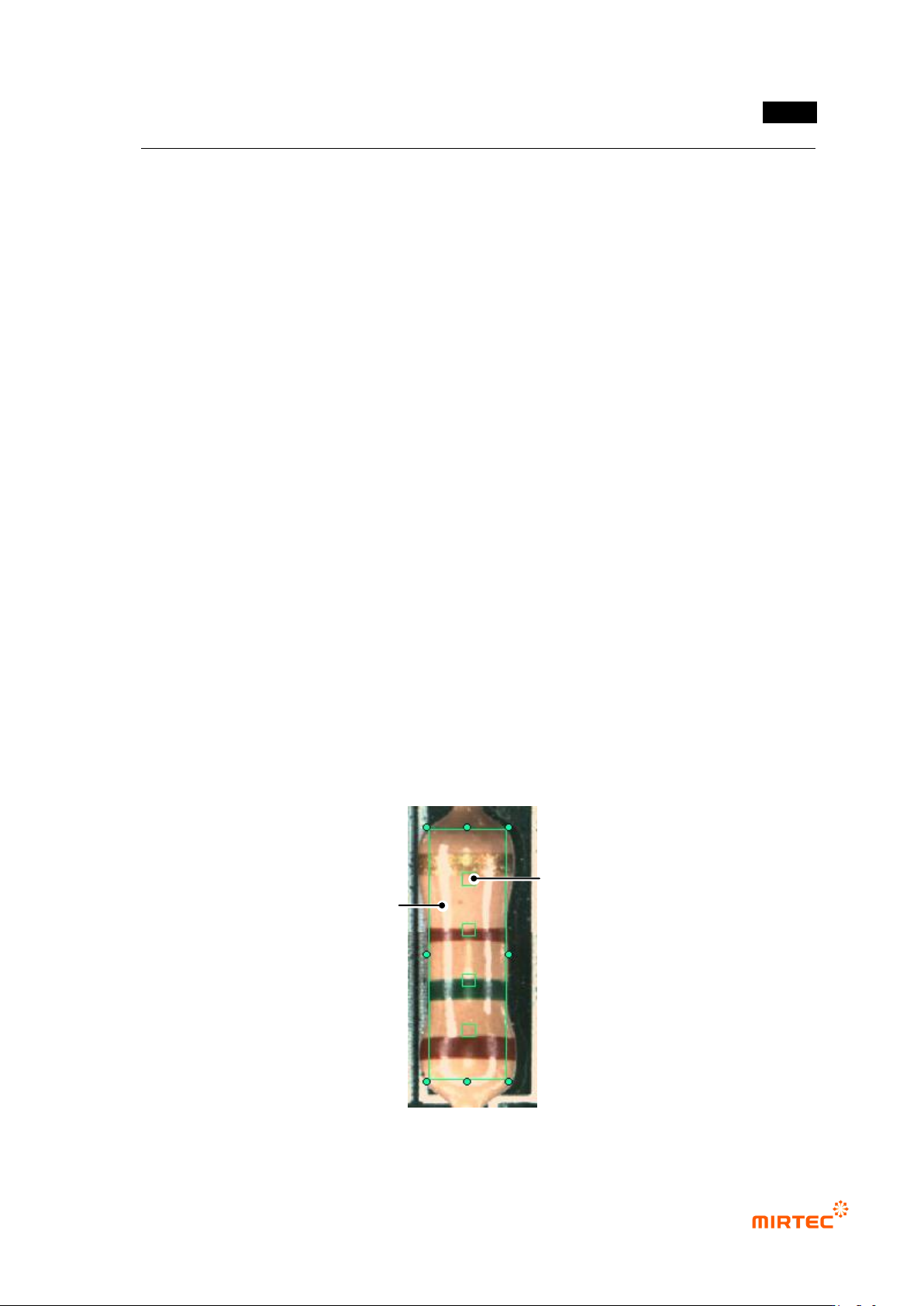
[Figure 5-200 Creation of resistance color band inspection window]
White regular reflection light
Color band inspection area
MV-9 User Manual
5-166
⑦ Group mounting window and resistance color band window into „Group component‟.
⑧ If there are components with same resistance on many parts of substrate, add it in the library,
too.
3) Inspection result in status window
For direct inspection of inspection window that completed teaching, select both of mounting
window and resistancecolor band window at the same time using selection button ( ) and select
„inspect‟ in popup menu displyed by clicking right button of the mouse to displaythe following
inspection result in status window in the main screen.
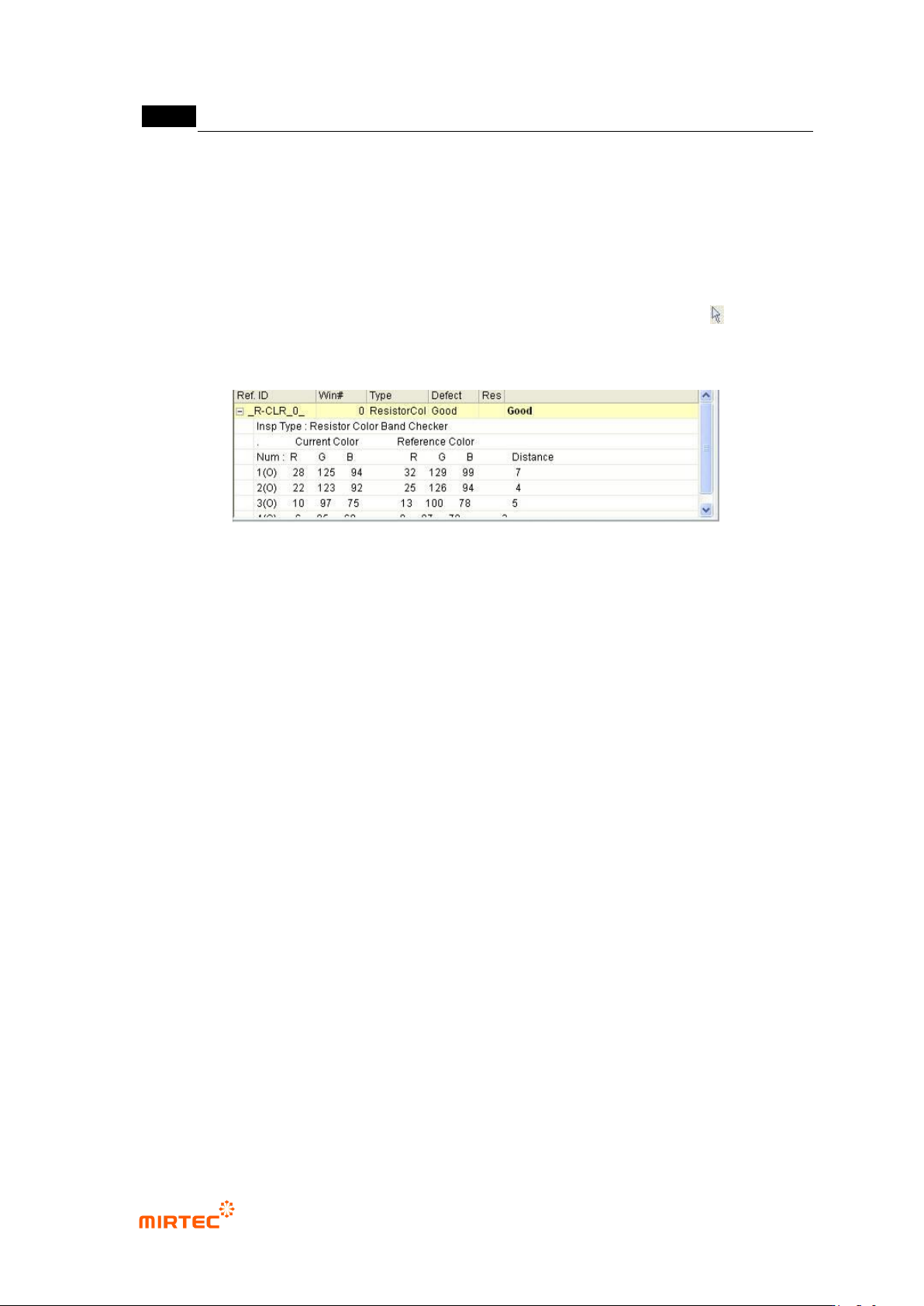
[Figure 5-201 inspection result screen]
Inspection type
This is to display current inspection type.
Current color
Display color of resistance color band inspection window that is currently inspected by color
band order in RGB value.
Reference color
This means inspection reference color. In other words, display resistance color band color of
golden board by RGB value for each detected color band order.
Color distance
This means relative distance of reference color and current color. In case of occurrence of
false defect, adjust min distance in color input window or add reference color to adjust it.