MV-9_Chapter 5. Teaching.pdf - 第259页
错误 ! 使用“开始” 选项卡将 제목 2 应用于要在此处显示的文字。 错误 ! 使用“开始”选项卡将 제목 2 应用 于要在此处显示的 文字。 . 5- 259 5.8.2 Lead Direction Set the direction of leads. 5.8.3 Setti ng of Parameters for Lead S eq . and B ridge Insp. Since the information sep …
MV-9 User Manual
5-258
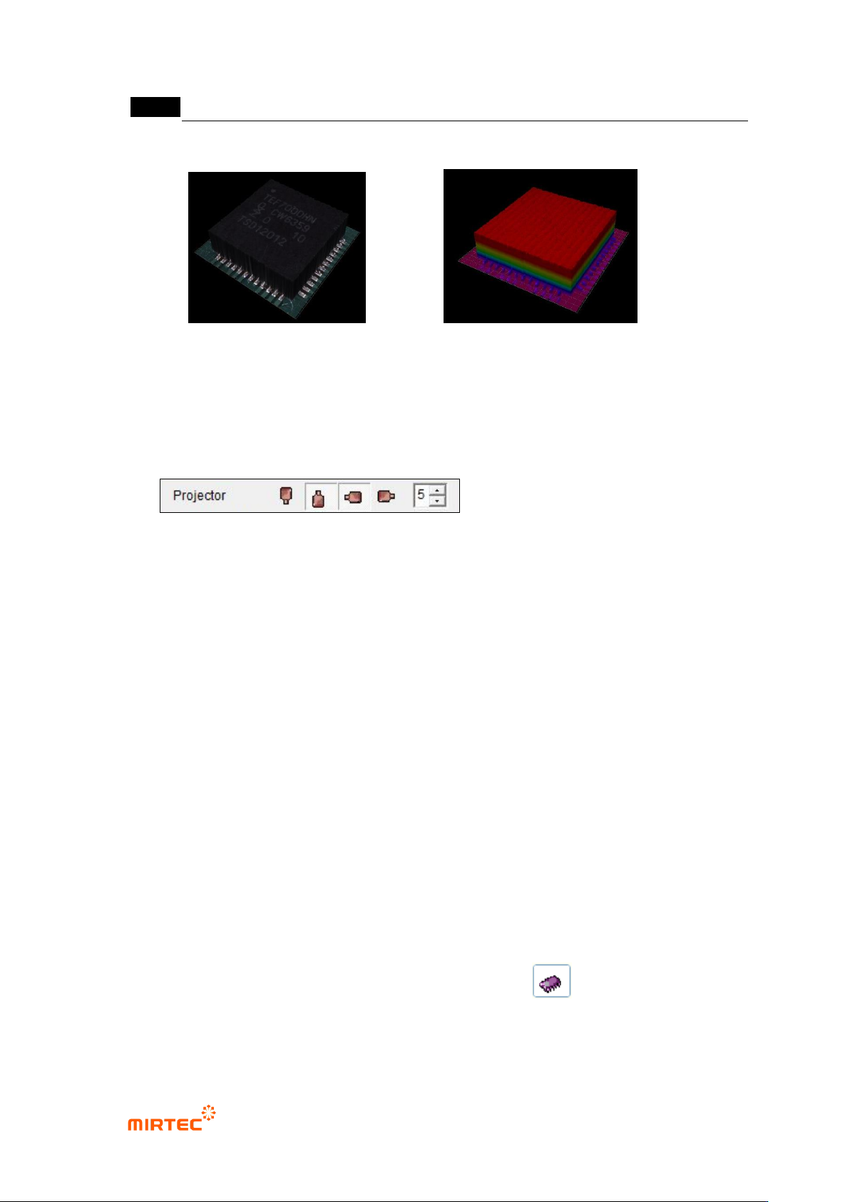
22 3D Model is shown while the Full Image is converted 3D Viewer tap.
<Texture Mapping> <Color Map>
5.7.9 Reliability Threshold
The height data with low reliability are treated as invalid values in order to remove the
shadow.
- In case the data reliability is lower than the set threshold, the data are treated as
invalid values.
- In case of black-series parts, it may seem that the measurement is not made since
most of them are treated as invalid ones due to the low reliability.
- In case the 3D model of black-series parts does not show the normal form, try again
by lowering the threshold value.
- If the threshold value gets too low, the shadow may not be removed and noise may
be expressed.
5.8 IC Lead
The objective is to inspect the lift of IC Leads.
5.8.1 Selection of Window for IC/Bridge Inspection
With the window button, select and add IC/Bridge Inspection..( ).
错误!使用“开始”选项卡将 제목 2 应用于要在此处显示的文字。错误!使用“开始”选项卡将 제목 2 应用
于要在此处显示的文字。 .
5-259
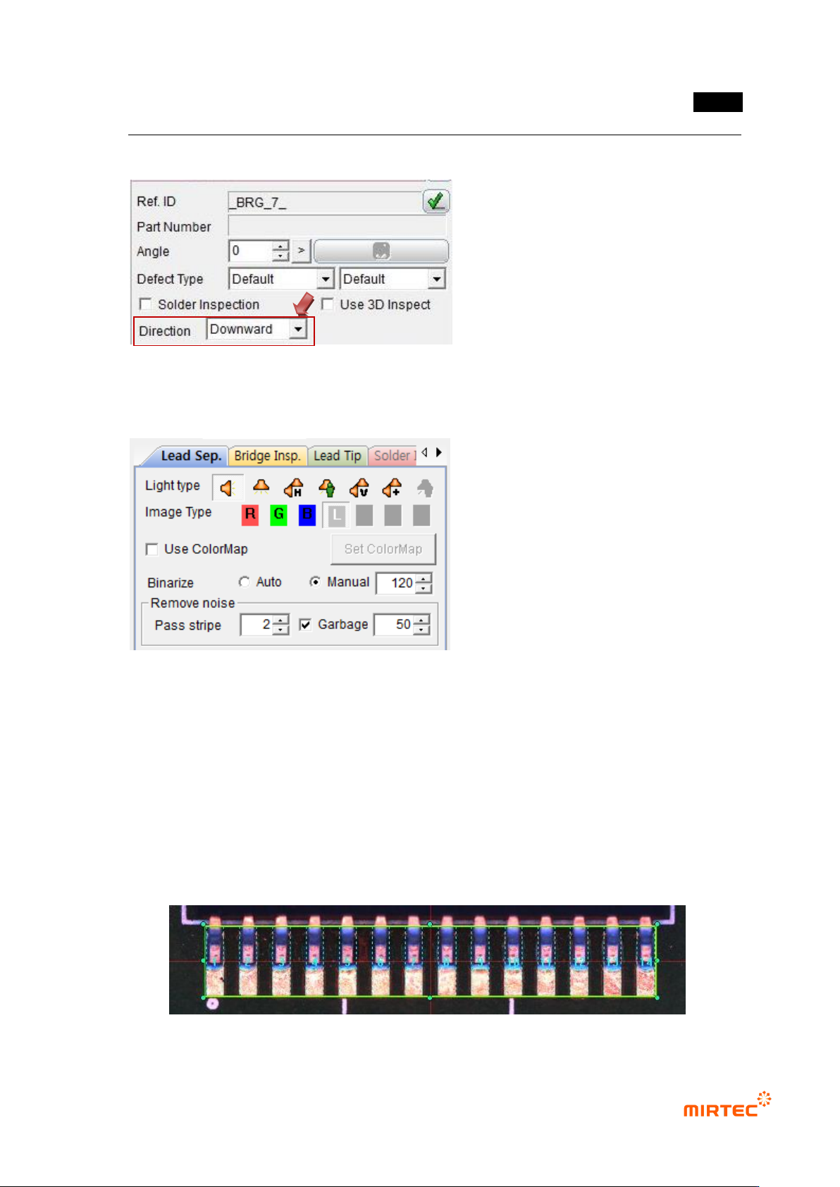
5.8.2 Lead Direction
Set the direction of leads.
5.8.3 Setting of Parameters for Lead Seq. and Bridge Insp.
Since the information separated from 2D Lead is used in the lift inspection of 3D Lead, first
set the parameters for Lead Sep. and Bridge Insp.
After completing the parameter setting, confirm through the trial inspection if the lead
separation is accomplished well.
* In case poor quality is found during Lead Sep. or Bridge Insp., do not conduct the lift
inspection of 3D Lead..
MV-9 User Manual
5-260
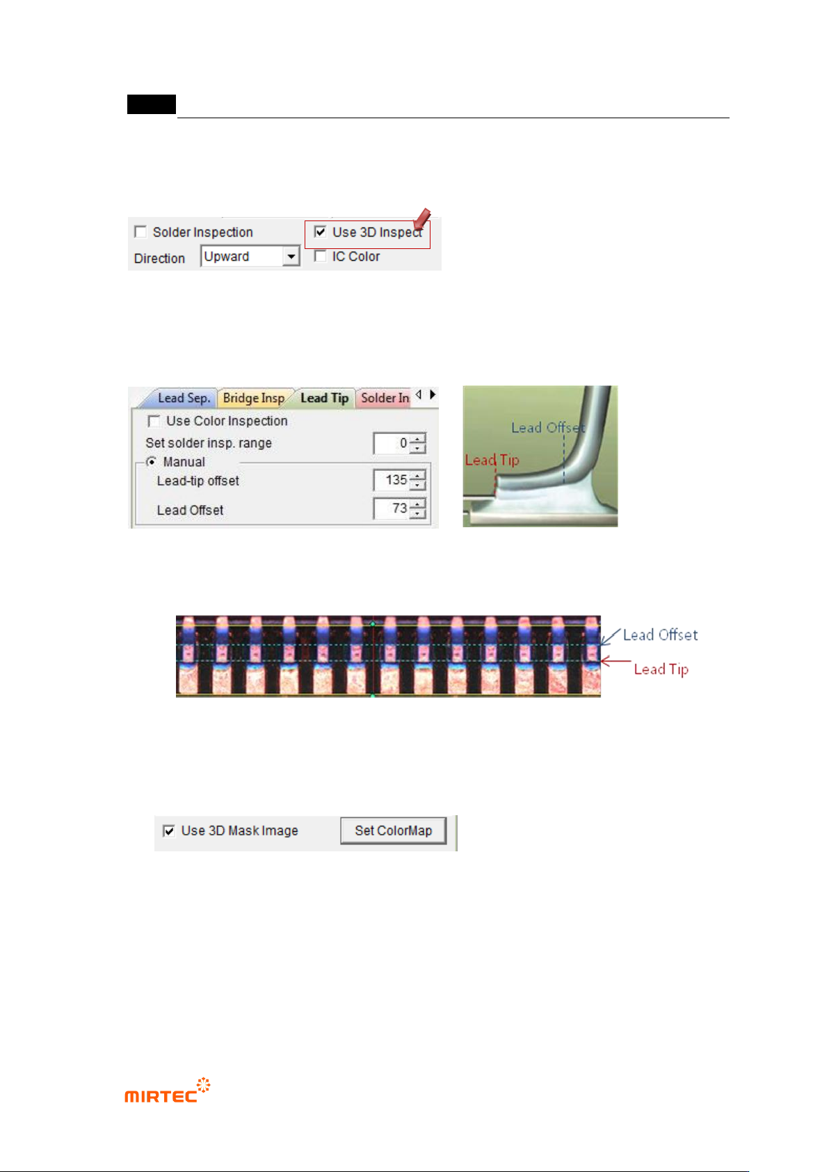
5.8.4 Setting of Lead-tip Offset and Lead Offset
If “Use 3D Inspection” is pressed, “Lead Tip Tab” is activated.
Set the parameters for Lead-tip offset and Lead offset.
Example)
5.8.5 Use Color Map
- At the end of the Lead Tip Tab, there is “Use 3D Mask Image” check box as shown
below:.
- If “3D Mask Image” is pressed, “Set Color Map” button is activated, If this button is
clicked, the window set for Color Map appears as shown below:
- By using the window set for Color Map, the lead region valid on 2D Image may be
separated and used in 3D inspection.