MV-9_Chapter 5. Teaching.pdf - 第213页
错误 ! 使用“开始” 选项卡将 제목 2 应用于要在此处显示的文字。 错误 ! 使用“开始”选项卡将 제목 2 应用 于要在此处显示的 文字。 . 5- 213 [Figure 5- 270 Y -shift in spection r esul t] ⑥ Shift inspection teaching and setting - Use bi nary inspect i on-position m ove i nspectio…
MV-9 User Manual
5-212
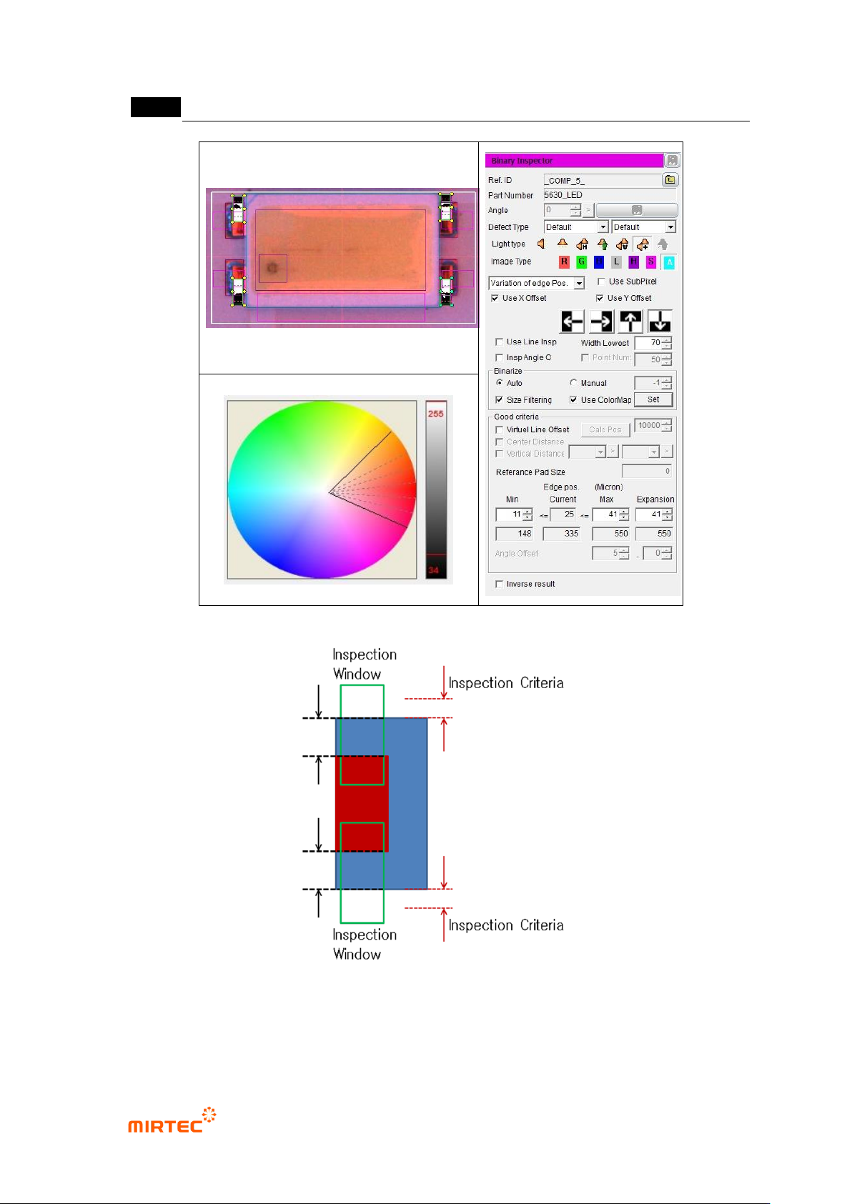
[Figure 5-268 Y-shift inspection setting and preview image]
[Figure 5-269 max setting of Y-shift inspection criteria]
错误!使用“开始”选项卡将 제목 2 应用于要在此处显示的文字。错误!使用“开始”选项卡将 제목 2 应用
于要在此处显示的文字。 .
5-213
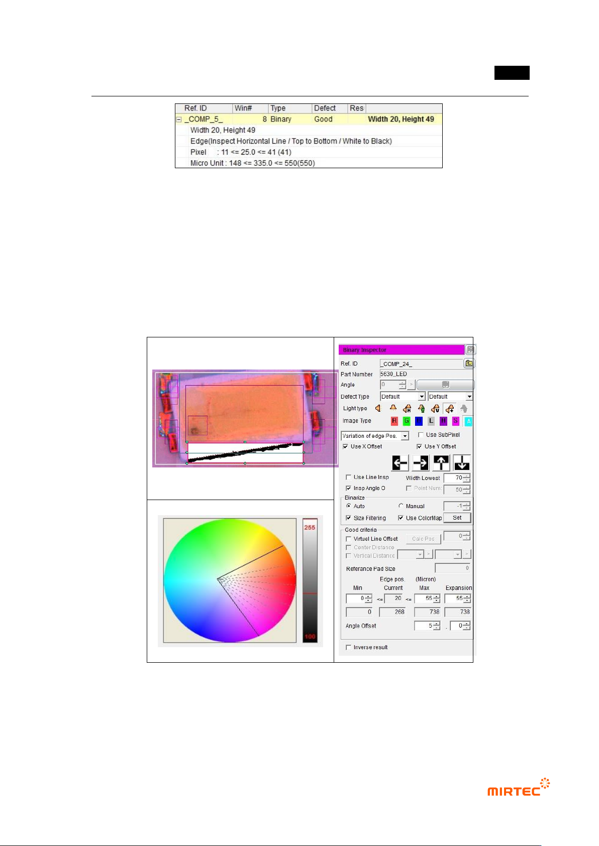
[Figure 5-270 Y-shift inspection result]
⑥ Shift inspection teaching and setting
- Use binary inspection-position move inspection window to detect rotation angle of package,
and angle inspection is used.
- For normal criteria, enter 0 for min and enter height value in the window for max. This is to
detect edge in the teaching window for angle inspection.
- To set angle, enter allowable angle in angle offset on the bottom by decimal point unit.
[Figure 5-271 shift inspection setting and preview image]
MV-9 User Manual
5-214
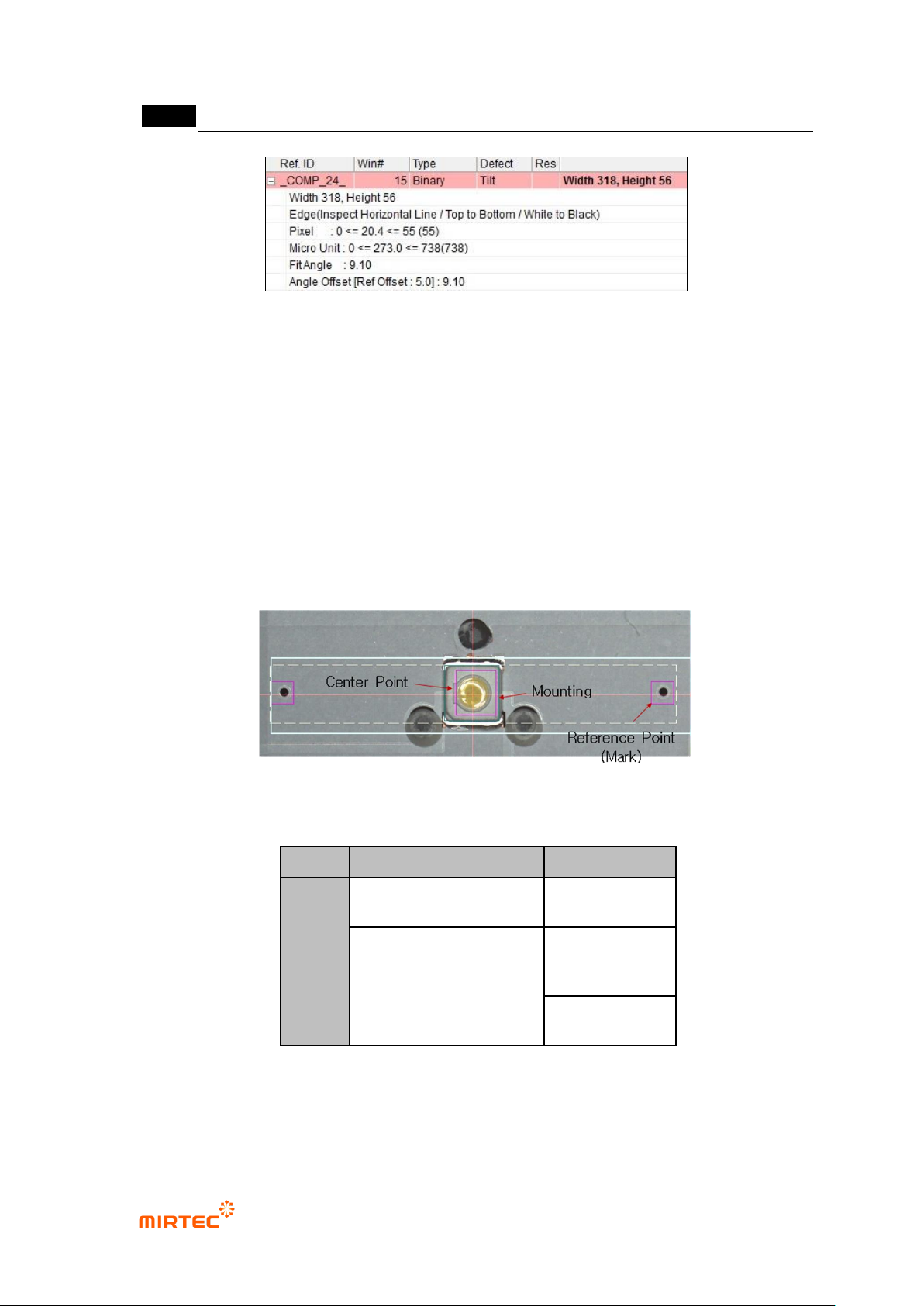
[Figure 5-272 shift inspection result]
5.4.3 Finding center position of LED package
- It is algorithm to measure center position of LED package mounted in BLU. Center position
of LED package is relative center position for reference point on the right and left of a
package. This algorithm is used for data to compare with center position of lens mounted
on LED package in post process rather than inspection purpose.
3) Teaching window
[Figure 5-273 teaching example]
[Table 5-19 center of LED package component search application algorithm]
applied algorithm
detection item
PKG
mounting inspection
position
compensation
Finding center of binary
inspection-component
Finding
component
center
reference point
(mark)
4) Teaching method
① Mounting inspection teaching and setting