MV-9_Chapter 5. Teaching.pdf - 第186页
MV -9 Use r Manual 5- 186 ① El ectrode inner blue ratio (Inner Blue Area <Electrode Area (% )) - Electrode inner blue ratio m eans ratio b l ue area inside of electrode based on electrode area. If it is below setting …

错误!使用“开始”选项卡将 제목 2 应用于要在此处显示的文字。错误!使用“开始”选项卡将 제목 2 应用
于要在此处显示的文字。 .
5-185
- In case there are defects like non-mounting, Manhattan, excessive solder, electrode
damage, foreign material that can occur in electrode area, electrode color ratio is to set
color ratio of electrode and normal range size of electrode to detect defect.
① Red Ratio (%): Set min ratio of Red in extracted electrode area.
② Blue Ratio (%): Set max ratio of Blue in extracted electrode area.
③ Long size (%) -: Set min ratio of normal range of electrode major axis. For example, if
electrode size is 100 and setting value is 30%, normal range of major axis of electrode will
be 70.
④ Long size (%) +: Set max ratio of normal range of electrode major axis. For example, if
electrode size is 100 and setting value is 30%, normal range of major axis of electrode will
be 130.
⑤ Short size (%): Set normal range ratio of electrode minor axis. For example, if electrode size
is 100 and setting value is 60%, normal range of minor axis of electrode will be 40 ~ 160.
⑥ Tilt Angle: set Tilt Angle in normal chip range.
- Electrode defect is for good/defect judgment by comparing area ratio of electrode area
(preview) expressed by red that is extracted in pad inspection → color map → Electrode
with reference value based on area of electrode area extracted from chip body.
- Short size and long size is to detect electrode size defect (electrode damage, non-
mounting, etc).
Short size and long size of electrode is defined by [(real value-reference value)
ⅹ100/reference value]. ratio of minor axis/major axis length of electrode extracted
during real inspection to minor axis/major axis length of electrode of calculated
normal chip during optimization process.
Real value is the size of electrode extracted from body tap for chip that is currently
being inspected, and reference value is saved in optimization and setting stage
during teaching or minor axis length of electrode and electrode major axis length on
the bottom of chip body tap.
(-) display in inspection result means that the size of electrode that is actually
extracted is below reference value.
Non-mounting criteria
- This parameter is to detect non-mounting. If blue area is smaller than setting ratio of
electrode area in area between pad offset and electrode, judge as good.
MV-9 User Manual
5-186
① Electrode inner blue ratio (Inner Blue Area <Electrode Area (%))
- Electrode inner blue ratio means ratio blue area inside of electrode based on electrode
area. If it is below setting value, judge as good.
② Electrode Inner Distance
- This will be activated only for 0402 chip. exclusive parameter for 0402 non-mounting
inspection.
- Default value is 180. Adjust it according to real size and pad size of 0402 chip that is real
inspection target.
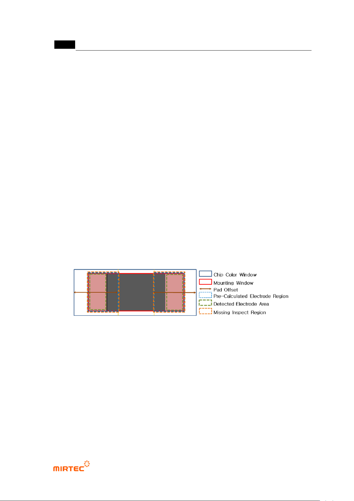
- As shown in [Figure 5-171] below, non-mounting inspection area will be set according to
the size of extracted electrode. non-mounting inspection area for left electrode is the left of
electrode area at chip of width direction, up and down is same, and the right side is area
that is expanded to between boundary line on the right side of electrode and pad offset. If
blue ratio is higher than reference value in this area, judge as non-mounting.
- Therefore, make sure to set it to make size of electrode extracted from chip body tap and
size of red electrode extracted by color map adjustment in [pad inspection → color map →
Electrode] selection are similar in the setting stage.
[Figure 5-228 chip color inspection detailed window area]
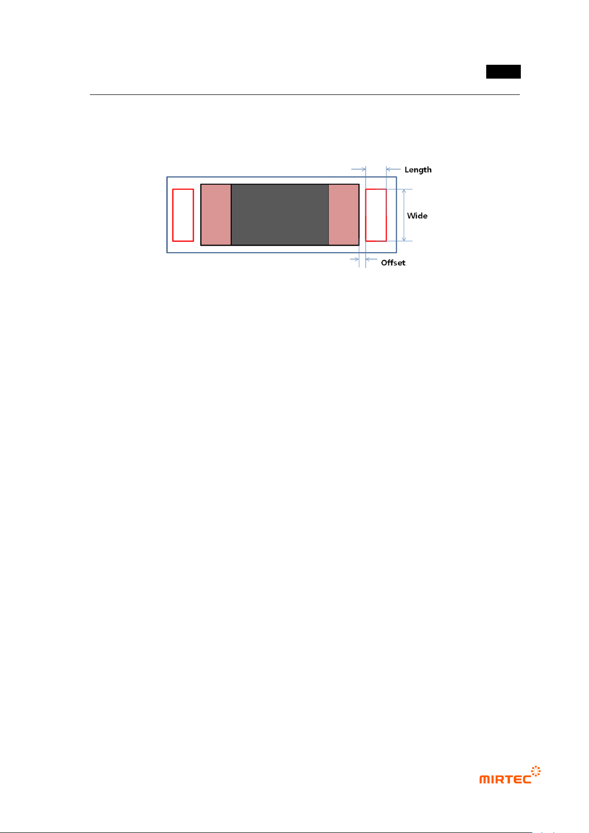
Lifted inspection (Center Rect)
- Generally, if lifted defect occurs, lifted inspection (Center Rect) shows red component next
to electrode. Hence, to detect lifted defect, as shown in [Figure 5-172], set size and normal
criteria of Center Rect using this function.
① Wide (%)
- This is to set width of Center Rect. To extract pad, set it to percentage to pad width, and
not to extract pad, set it to percentage to size of chip electrode.
② Length
错误!使用“开始”选项卡将 제목 2 应用于要在此处显示的文字。错误!使用“开始”选项卡将 제목 2 应用
于要在此处显示的文字。 .
5-187
- Length of Center Rect chip length direction.
③ Offset
- This is to set the away distance of Center Rect based on electrode end.
[Figure 5-229 lifted inspection (Center Rect) setting item]
④ Blue Ratio (%): set Blue ratio in Center Rect.
⑤ Red Ratio (%): set Red ratio Center Rect.
⑥ Cold Solder Check
- Set whether to conduct cold solder inspection for chip. In general, for lifted inspection, set
color map to include yellow area (cold solder) in [pad inspection → color map → Pad].
- After setting to detect cold solder defect, If many false defects are occurred during lifted
inspection for Center Rect, separate color map for lifted inspection and cold solder
inspection. The following is separation method.
Exclude yellow area from Pad color map
Select Cold Solder Check in pad inspection tap
Select cold solder in color map, and set only yellow area for cold solder inspection
in color map
- In general, most of cold solder defects displayed in yellow between electrode and pad.
Sometimes, the defect displayed in sky-blue, orange, or pink. Therefore, if necessary,
select pentagon in color map and adjust it as shown in the [Figure 5-247] below.