MV-9_Chapter 5. Teaching.pdf - 第168页
MV -9 Use r Manual 5- 168 ⑦ Set reference value for inspect io n item s and good/defect judgment for each item i n norm al criteria 2) T eaching example of repres ent ati ve component [Figure 5- 202 T eachin g example of…

错误!使用“开始”选项卡将 제목 2 应用于要在此处显示的文字。错误!使用“开始”选项卡将 제목 2 应用
于要在此处显示的文字。 .
5-167
5.3.12 IC offset inspection window
- IC offset inspection is algorithm to inspect status (lead offset, lead shift, lead tip offset) of
IC lead and mounting status (Shift, Tilt) of IC after mounting.
- Besides default light, sub light can be used for lead inspection and pad inspection, and
false defect that can occur under default light can be reduced.
1) Teaching method
① Click <IC offset inspection window> button among operating buttons, and draw window at IC
position of IC desired to be inspected. In general, draw window that is larger than pad area
desired to be inspected.
② Teaching tap teaching
- Select preview in operation window.
- Set light type and image type and binarization for good separation of lead.
- Adjust stripe width and area for noise removal.
- Set number of lead, lead tip, offset, and pad length.
③ Lead inspection tap setting
- Select default light tap, and select light type and inspection type (image type) for lead
inspection.
- Select auto or manual for binarization method. If „manual is set, set binarization value to
clearly display lead.
- Set stripe width and area for noise removal.
- Set search start position, search range, and contrast level for lead inspection. If „auto‟ is
set, check search range auto extraction.
④ Pad inspection teaching
- Select default light tap, and select light type and inspection type (image type) for pad
inspection.
- Select auto or manual for binarization method. If „manual is set, set binarization value to
clearly display pad.
- Set stripe width and area for noise removal.
- Set search start position, search range, and contrast level for pad inspection.
⑤ Check whether to use sub light or not. Select sub light tap that is activated in lead inspection
and pad inspection to set parameter. (light type and image type change)
⑥ Select monitoring option.
MV-9 User Manual
5-168
⑦ Set reference value for inspection items and good/defect judgment for each item in normal
criteria
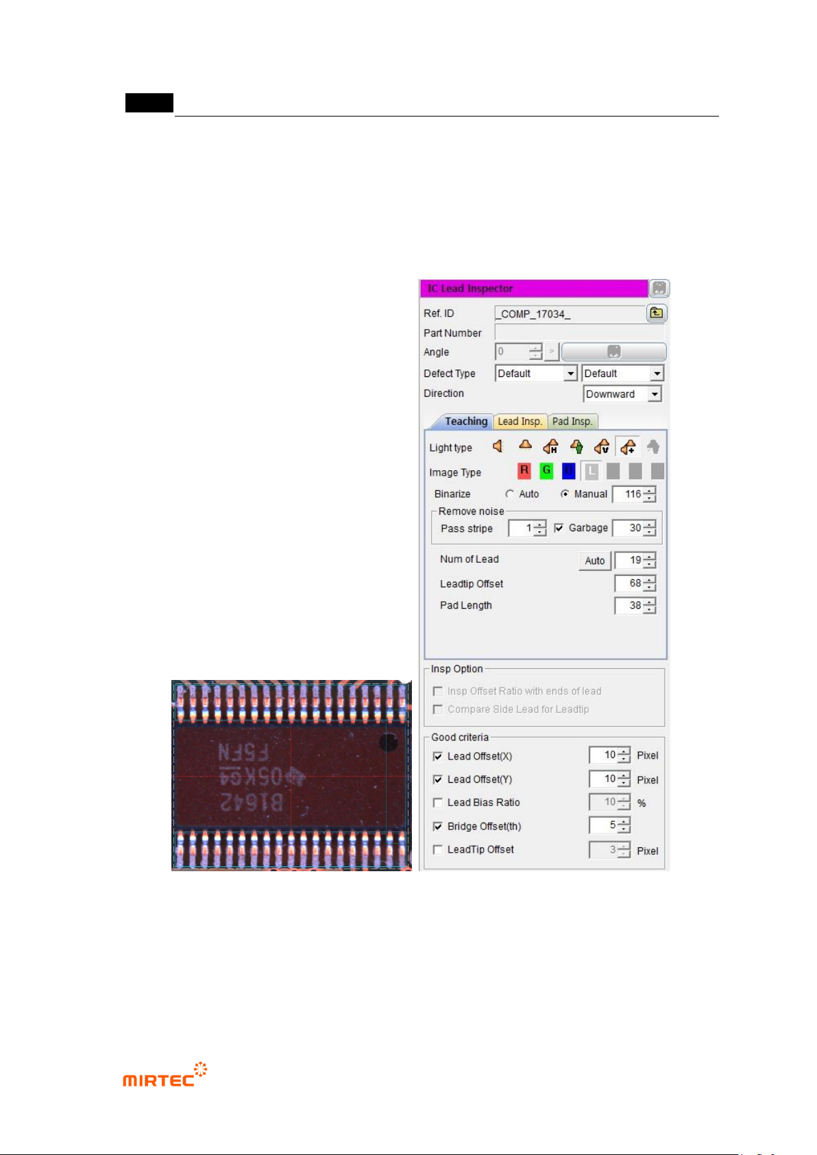
2) Teaching example of representative component
[Figure 5-202 Teaching example of mounting inspection window]
3) Inspection parameter
Reference name
- Refer to „reference name‟ in „5.3.1 mounting inspection window‟ excepting shape.
错误!使用“开始”选项卡将 제목 2 应用于要在此处显示的文字。错误!使用“开始”选项卡将 제목 2 应用
于要在此处显示的文字。 .
5-169
Component name
- Refer to „component name‟ in „5.3.1 mounting inspection window‟‟.
Rotation angle
- Refer to „rotation angle‟ in „5.3.1 mounting inspection window‟‟.
Defect type
- Refer to „defect type‟ in „5.3.1 mounting inspection window‟‟.
Direction
- Select lead direction.
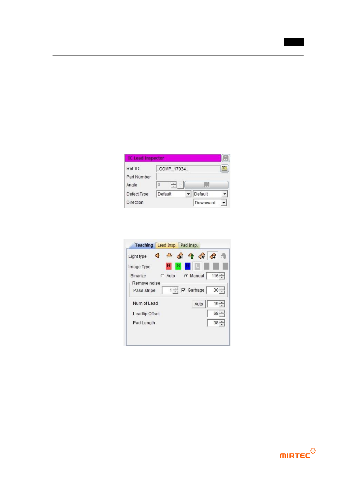
[Figure 5-203 Default parameter]
Teaching tap parameter
[Figure 5-204 Teaching tap parameter]