MV-9_Chapter 5. Teaching.pdf - 第223页
错误 ! 使用“开始” 选项卡将 제목 2 应用于要在此处显示的文字。 错误 ! 使用“开始”选项卡将 제목 2 应用 于要在此处显示的 文字。 . 5- 223 [Figure 5- 287 hierarchy structure of inspection window] module ad d T o r educe te aching and debugging tim e dur ing connecting module…
MV-9 User Manual
5-222
[Figure 5-284 frame move]
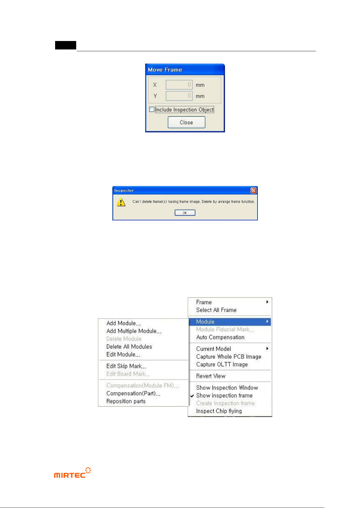
Frame delete
This function is to delete a selected frame. After deleting frame, end frame delete using frame
arrangement function in the screen below.
[Figure 5-285 frame delete end screen]
6) Module related function
If there are many modules on 1 PCB, the following functions are used to add, delete and edit
module. The following is module popup menu and PCB hierarchy structure during model
teaching.
[Figure 5-286 module menu]
错误!使用“开始”选项卡将 제목 2 应用于要在此处显示的文字。错误!使用“开始”选项卡将 제목 2 应用
于要在此处显示的文字。 .
5-223
[Figure 5-287 hierarchy structure of inspection window]
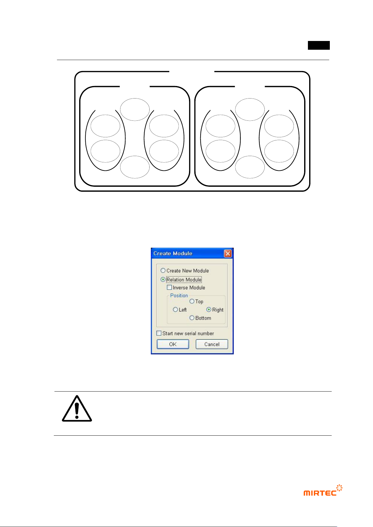
module add
To reduce teaching and debugging time during connecting module substrate teaching, use this
function to equally apply teaching for base module to other modules.
[Figure 5-288 new module creation]
Caution
To add module, teaching of compensation mark of base module must be
conducted. If there is no compensation mark on base module, compensation
mark window must be created at specific area that has same function with
compensation mark.
new module creation
PCB Model
Module
Part
Inspection
window
Inspection
window
Part
Inspection
window
Inspection
window
Inspection
window
Inspection
window
Module
Part
Inspection
window
Inspection
window
Part
Inspection
window
Inspection
window
Inspection
window
Inspection
window
MV-9 User Manual
5-224
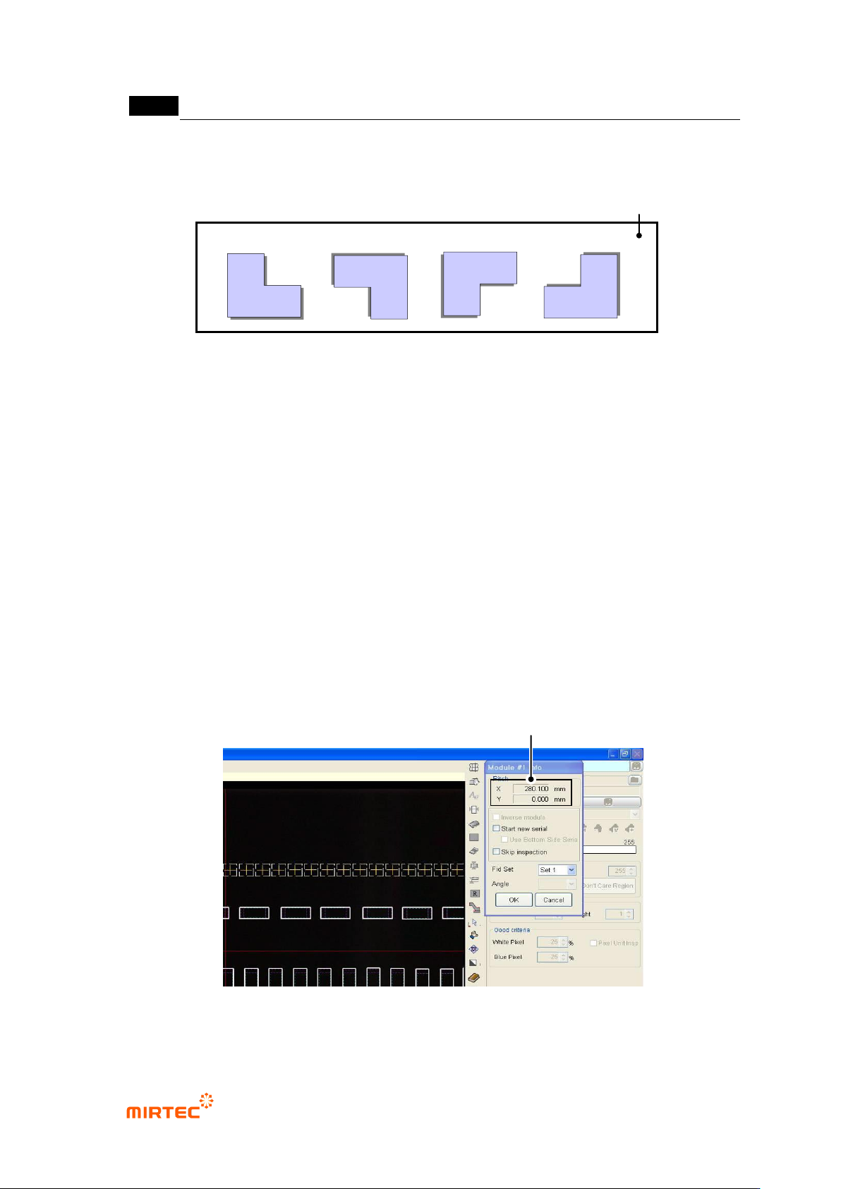
This function is used when component of base module is different from configuration or used for
teaching for 90° rotated module.
[Figure 5-289 Example of new module creation function]
Create compensation mark after moving module to a new area and teaching for conduct the
relevant component.
Creating connecting module
i. Use this when module to be added is same with component configuration of base
module, and select one of up/down/left/right direction for position based on base
module.
ii. In case of reverse module, check at „reverse module‟.
iii. Robot will automatically move to the first compensation mark position of reference
module, and compensation mark window will be displayed at the center of frame
image screen.
iv. To display window that completed teaching in frame image screen, select random
frame in whole image screen.
v. Move robot to the position where there is component of added module while
pressing the left button of mouse in frame image screen, and click <OK> button in
module screen to finish connecting module creation.
[Figure 5-290 Connecting module creation screen]
Offset Distance between Standard Module and Creation Module
Basic module
Reverse module
New module
PCB
New module