MV-9_Chapter 5. Teaching.pdf - 第140页
MV -9 Use r Manual 5- 140 Screen Description Defect due to blue pixel ratio of fillet area and red pi x el ratio of shoulder Defect due to r ed pixel r at i o of lead tip distance and shou l der Defect w hen red pixel ra…
错误!使用“开始”选项卡将 제목 2 应用于要在此处显示的文字。错误!使用“开始”选项卡将 제목 2 应用
于要在此处显示的文字。 .
5-139
Tip: distance between average value of tip position of all lead and lead tip of
inspection lead
Shoulder: color ratio of lead shoulder of inspection lead
- Pad
Area: effective pad area of inspection lead (%)
Red: red pixel ratio of inspection lead (%)
Lead and Inspection Result
Image
Preview Image of Fillet
Inspection
Preview Image of Pad
Inspection
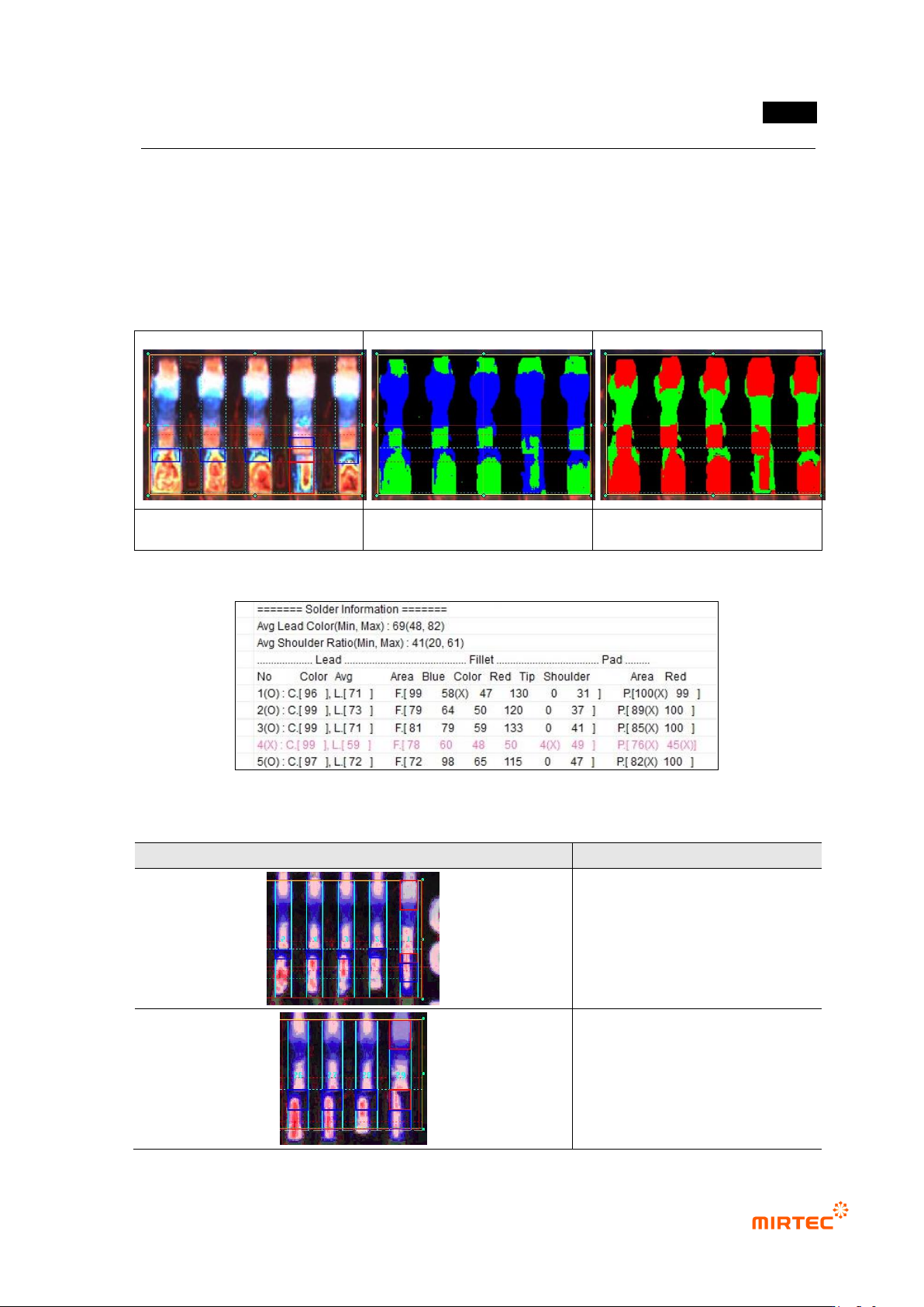
[Figure 5-164 Solder amount inspection (advanced inspection) result image]
[Figure 5-165 solder amount inspection (advanced inspection) result screen]
[Table 5-14 result screen after fillet inspection]
Screen
Description
Defect due to red pixel ratio of
lead tip distance and shoulder
part
Defect due to red pixel thickness
of lead and pad and red pixel
ratio of shoulder part
MV-9 User Manual
5-140
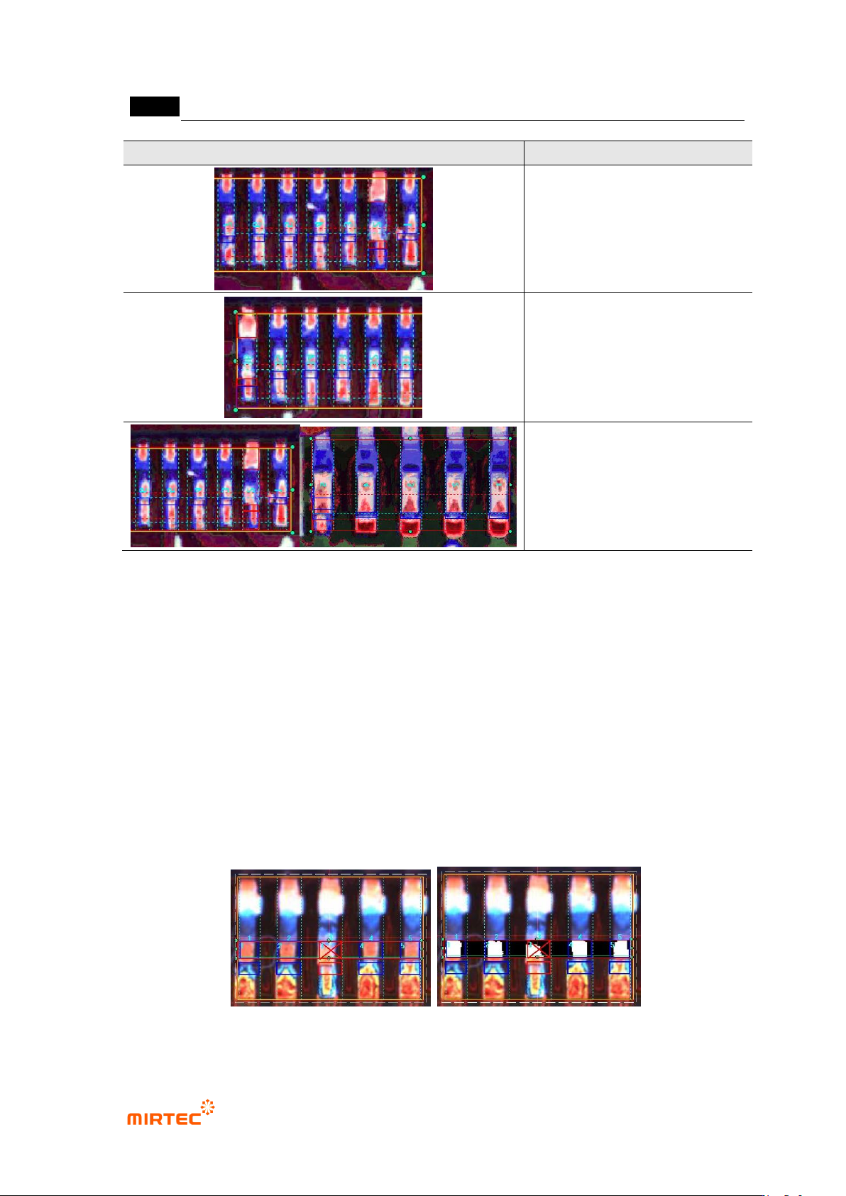
Screen
Description
Defect due to blue pixel ratio of
fillet area and red pixel ratio of
shoulder
Defect due to red pixel ratio of
lead tip distance and shoulder
Defect when red pixel ratio of pad
area is below reference value
IC color result
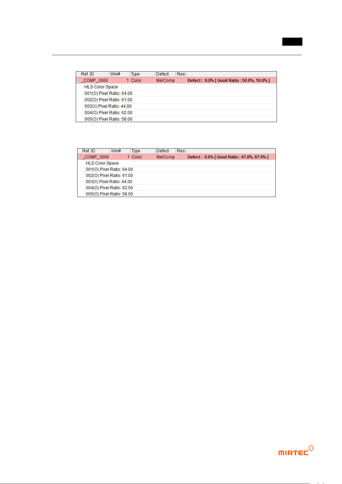
- Pixel ratio inspection
Pixel ratio of color inspection area is displayed in each lead. If it is above normal
ratio, judge as good.
Normal ratio: the first value is value entered in pixel ratio. Min value to judge as
good.
- IC average ratio inspection
Pixel ratio of color inspection area is displayed in each lead. If it is within normal
ratio range, judge as good.
Normal ratio: average value and pixel ratio of lead, calculated by IC average ratio
inspection input value.
[Figure 5-166 Solder amount inspection (advanced inspection) result image and preview image]
错误!使用“开始”选项卡将 제목 2 应用于要在此处显示的文字。错误!使用“开始”选项卡将 제목 2 应用
于要在此处显示的文字。 .
5-141
[Figure 5-167 pixel ratio inspection result]
[Figure 5-168 IC average ratio inspection result]
5.3.7 Color inspection window
- Color inspection window is used to inspect items like non-mounting and/or wrong mounting
of component using difference of color of mounted component.
1) Teaching method
① Click <color inspection window> button among operating buttons and draw inspection
window in inspection target area. position for color in inspection window will be automatically
displayed at color coordinator.
② Horizontal + vertical light will be selected for light type. Position for color in inspection
window will be automatically refreshed at color coordinator.
③ Select whether to conduct X coordinate compensation, Y coordinate compensation.
④ Select one of color coordinators (RGB, HSV, LUV) for color inspection.
⑤ Select whether to conduct grid inspection, and enter number of grid width and height. To use
grid inspection, enter normal ratio for good/defect judgment.
⑥ select whether to conduct pixel ratio inspection not color inspection (ratio of pixel that has
color designated in inspection area, displayed by white pixel when preview is selected.).
⑦ Enter normal range.
⑧ Select whether to judge as good when defect is detected.