MV-9_Chapter 5. Teaching.pdf - 第203页
错误 ! 使用“开始” 选项卡将 제목 2 应用于要在此处显示的文字。 错误 ! 使用“开始”选项卡将 제목 2 应用 于要在此处显示的 文字。 . 5- 203 reference point 1 because distance between str aight li ne 2 and vertical edge position i s defin e d as x-shift . Added to that , i t is …
MV-9 User Manual
5-202
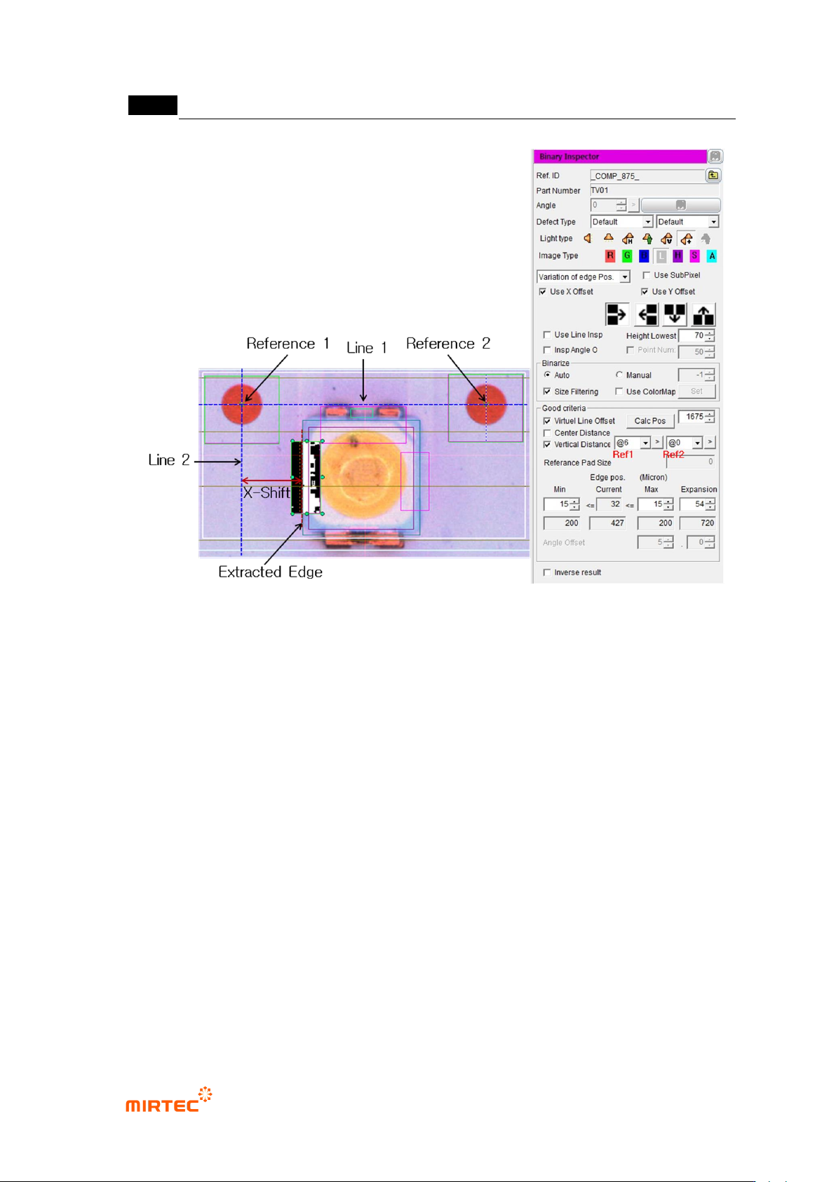
[Figure 5-252 X-shift definition and inspection setting]
- Setting for X-shift inspection
To inspect X-shift, create binary inspection window on exterior of LED package to
detect edge of vertical direction, and select position move inspection. Draw binary
inspection window to match window center with package edge. Draw window larger
than tolerance*2 to detect edge.
Adjust color map to properly create edge through preview.
Enter „0‟ for min value and window size for max value (If 100 is entered,
automatically changed to max size.) to check if LED edge is properly detected
through trial inspection.
Select „virtual line offset‟ and select „vertical direction distance‟. (Reference: To
select virtual line offset is to create virtual straight line 1 using reference point 1 and
reference point 2, and to select vertical direction distance is to create virtual straight
line 2 and calculate x-shift value.)
Firstly, register window close to package edge to be inspected as reference point 1,
and register reference point 2. (Reference: register reference point close to edge as
错误!使用“开始”选项卡将 제목 2 应用于要在此处显示的文字。错误!使用“开始”选项卡将 제목 2 应用
于要在此处显示的文字。 .
5-203
reference point 1 because distance between straight line 2 and vertical edge
position is defined as x-shift. Added to that, it is because straight line 2 is defined as
straight line that crosses central point of reference point 1. @6 is window No of
reference point1.)
Enter reference distance of normal sample in position calculation referring to design
specification. (click position calculation to display calculated x-shift value of the
current LED package.)
Enter X-shift tolerance in min and max in pixel unit based on inspection criteria.
(Caution: min and max of boundary line position item has different meaning with that
of general position move inspection when virtual line offset is checked. For general
position error inspection, set min/max of range in which edge has to be detected.
However, real pixel value for tolerance when virtual line offset is checked. In other
words, if tolerance is ±200um, enter 15 for min and enter 15 for max. number that is
displayed immediately below is um unit of input pixel value.)
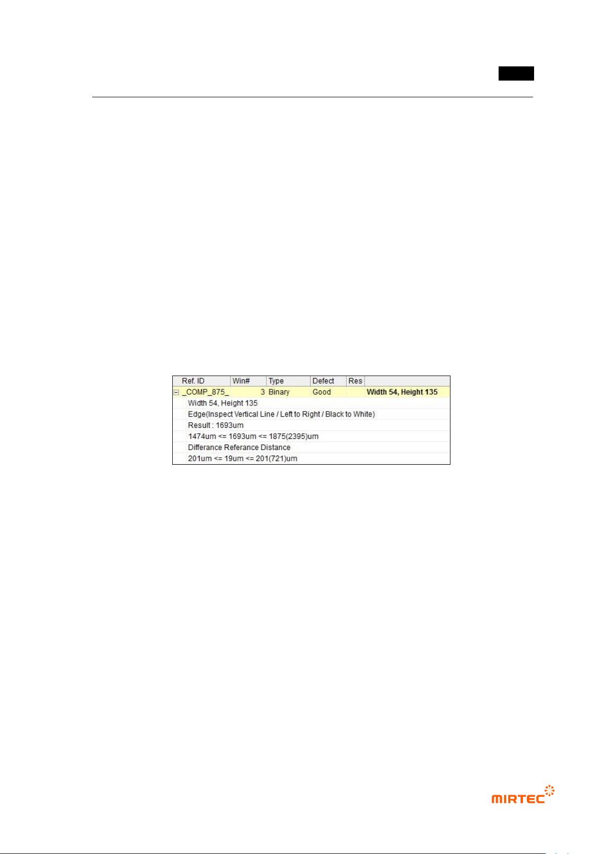
[Figure 5-253 X-shift inspection result]
⑥ Teaching and setting for Y-shift inspection
- Teaching and setting for Y-shift inspection is same with teaching and setting procedure for
X-shift inspection. Different point is that any reference point firstly can be registered
regardless of position of reference point and edge, and we do not use vertical direction
distance.
MV-9 User Manual
5-204
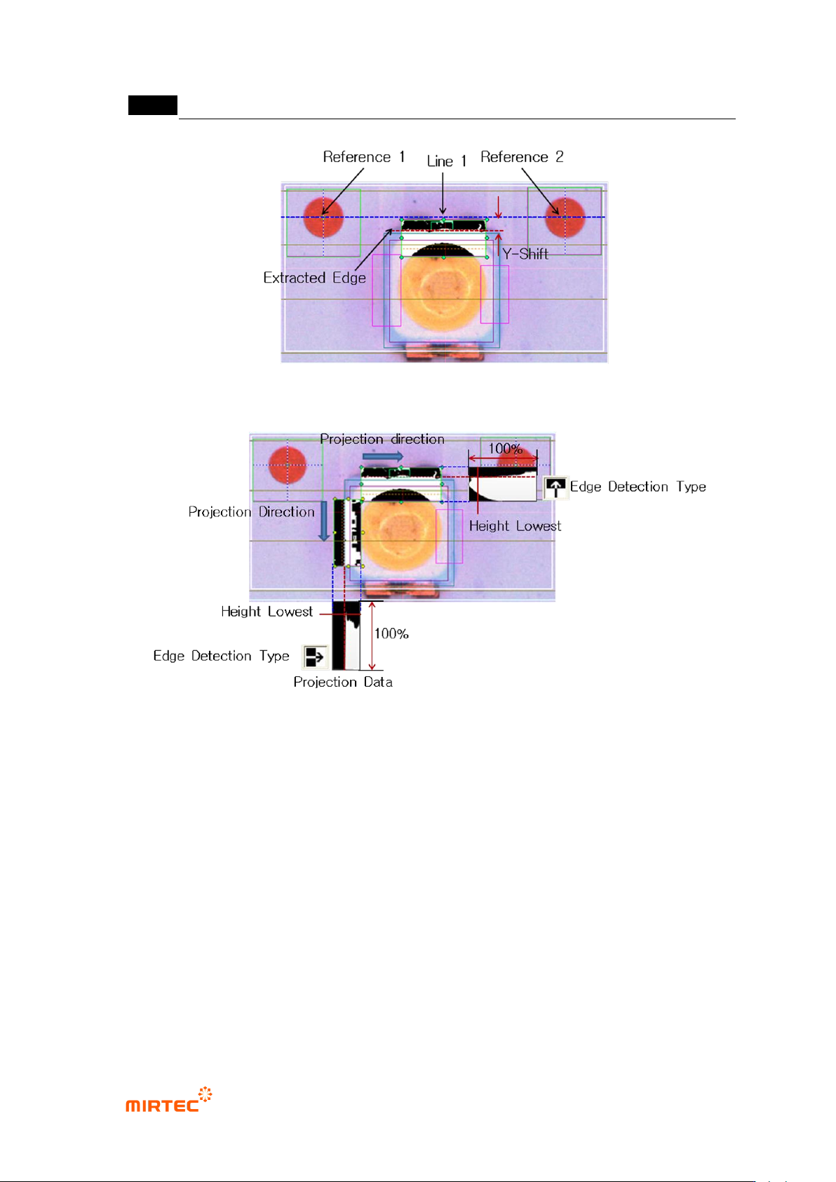
[Figure 5-254 Y-shift definition]
[Figure 5-255 edge detection example for X/Y-shift inspection]
⑦ Teaching and setting shift inspection
- Binary inspection-position move inspection window is used to detect rotation angle of
package, and check at angle inspection to use it.
- For angle setting, enter allowable angle in angle offset on the bottom by decimal point unit.