MV-9_Chapter 5. Teaching.pdf - 第208页
MV -9 Use r Manual 5- 208 [Figure 5- 260 Foreign material inspection setting and preview image] [Figure 5- 261 ‘Don’t care region’ settin g] [Figure 5- 262 foreign material inspection result]
错误!使用“开始”选项卡将 제목 2 应用于要在此处显示的文字。错误!使用“开始”选项卡将 제목 2 应用
于要在此处显示的文字。 .
5-207
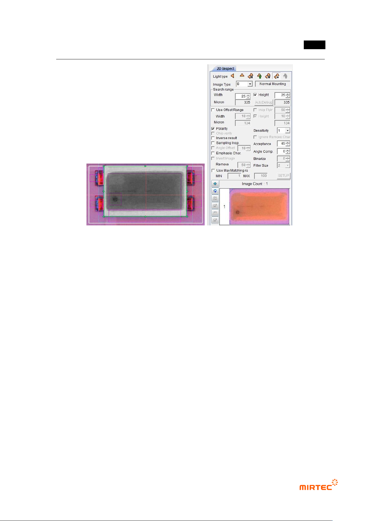
[Figure 5-259 mounting inspection setting and preview image]
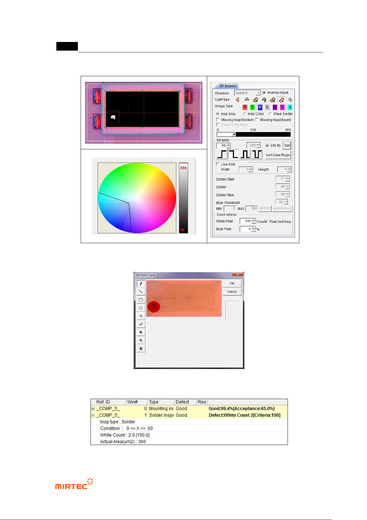
② Teaching and setting foreign material inspection (solder inspection)
- Foreign material inspection is to inspect foreign material on the surface of fluorescent
substance. For this purpose, we use solder inspection window.
MV-9 User Manual
5-208
[Figure 5-260 Foreign material inspection setting and preview image]
[Figure 5-261 ‘Don’t care region’ setting]
[Figure 5-262 foreign material inspection result]
错误!使用“开始”选项卡将 제목 2 应用于要在此处显示的文字。错误!使用“开始”选项卡将 제목 2 应用
于要在此处显示的文字。 .
5-209
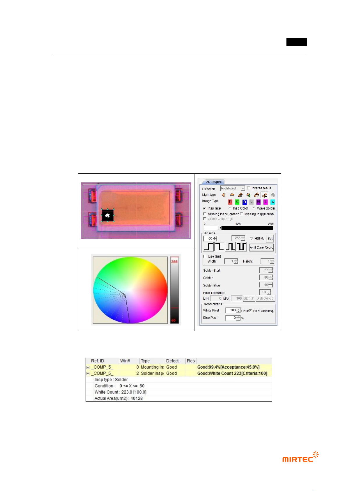
③ Polarity inspection (solder inspection) teaching and setting
- For Polarity inspection, detect polarity of mounted LED package and judge Polarity. In
general, TV has a polarity mark (so called chamfering) on one corner of package. However,
detection status differs from package. Hence, detect electrode inside LED using solder
inspection algorithm.
- Select general inspection, and select light type and image type in which electrode clearly
appears.
- Set color map and binarization value for good electrode separation through preview.
- Select pixel unit inspection, and enter min value for good/defect judgment by pixel unit.
[Figure 5-263 Polarity inspection setting and preview image]
[Figure 5-264 Polarity inspection result]