MV-9_Chapter 5. Teaching.pdf - 第42页
MV -9 Use r Manual 5- 42 - Solder start S et start position of solder inspection area . In general, set it to electrode end, and electrode i s not i ncluded . - Solder width Th i s is to set width of so l der i nspec…
错误!使用“开始”选项卡将 제목 2 应用于要在此处显示的文字。错误!使用“开始”选项卡将 제목 2 应用
于要在此处显示的文字。 .
5-41
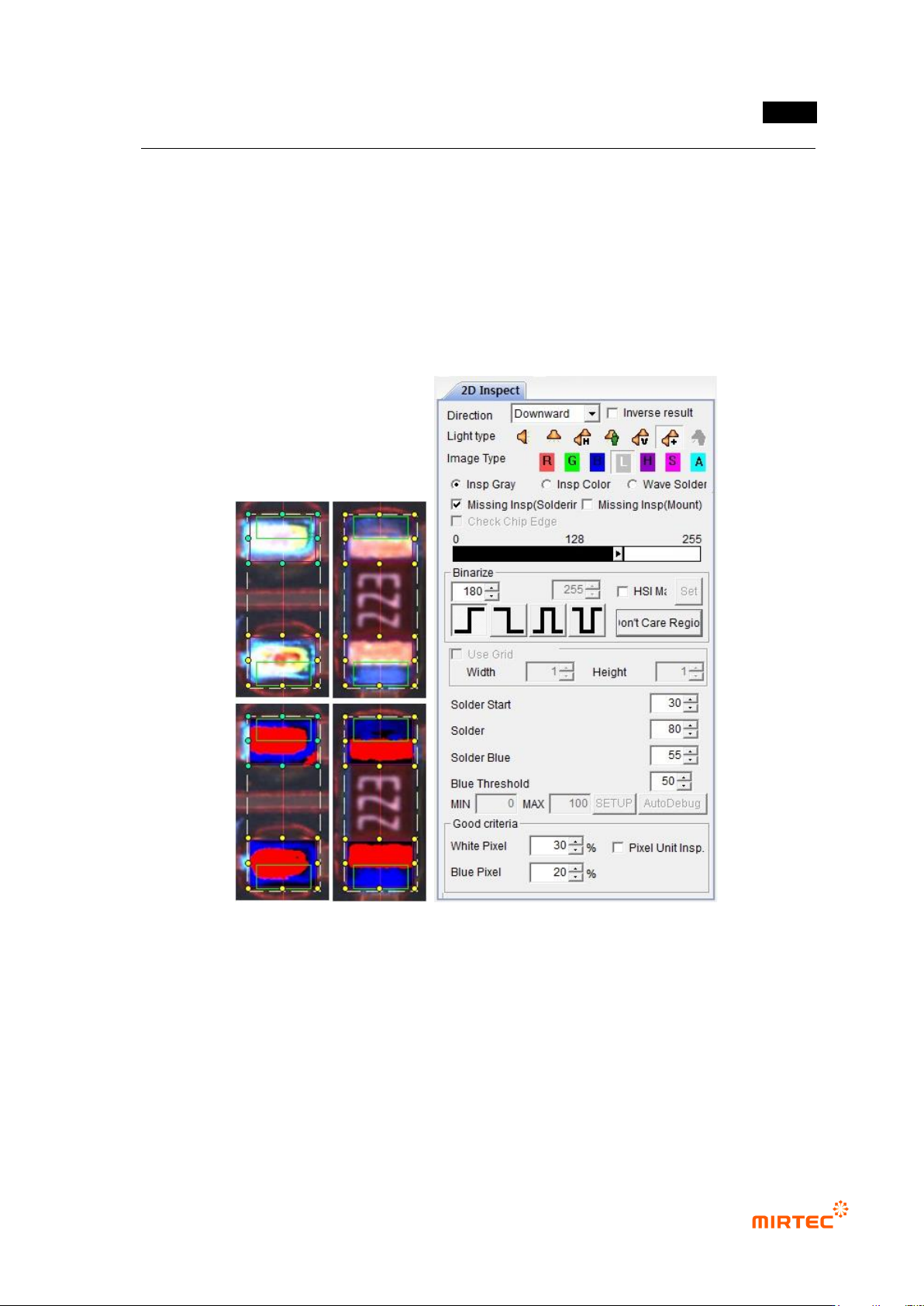
(c) Click non-mounting inspection (soldering) in parameter window.
(d) Set solder start area. Green area in inspection window expands toward electrode. set
start area not to include electrode but to include solder area
(e) Set solder width. Length of green area in inspection window will be adjusted to the width
direction of electrode.
(f) Adjust binarization value and solder blue ratio so that electrode can be separated to red
and solder area can be separated to blue.
(g) Enter normal criteria.
[Figure 5-44 Soldering inspection (basic) window creation screen and preview image]
② Parameter in non-mounting inspection (mounting) window
- Non-mounting inspection (mounting)
This is used to detect non-mounting defect during soldering status inspection at the rear
part of soldering process.
- Binarization
Set binarization value of red and blue.
MV-9 User Manual
5-42
- Solder start
Set start position of solder inspection area. In general, set it to electrode end, and
electrode is not included.
- Solder width
This is to set width of solder inspection area. Inspection window width will be set to
100%.
- Solder blue ratio
This is to set blue reference of solder. Blue and red ratio. Based on 50, if it is below 50,
it is red series. If it is above 50, it is blue series. Remove solder with value below
reference value.
Electrode will be displayed in red + white in color light, and solder is displayed in blue.
Hence, set it within approximately 50 ~ 60 range.
- Blue binarization
This is to set reference value for binarization of blue range judged by solder blue ratio.
- White pixel ratio
This is to set good/defect judgment reference value white pixel ratio for solder area
(outer). If it is below reference value, judge as defect.
- Blue pixel ratio
This is to segment inner area (chip body direction, inner) and outer area (solder
direction, outer) based on center of red area (electrode). Calculate ratio of blue pixel in
each area.
Blue pixel ratio is defined by blue ratio in inner area comparing to blue ratio in outer
area. If it is higher than reference value, judge as defect. This means that blue ratio is
high at electrode and inward.
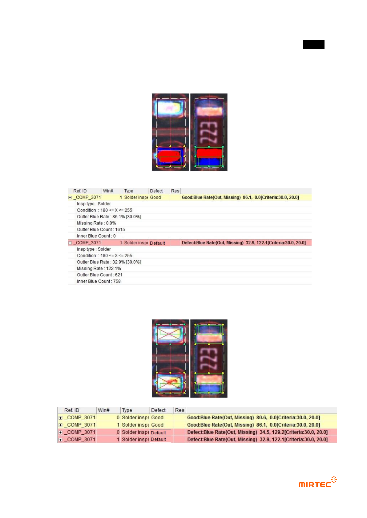
③ Non-mounting inspection (soldering) result in status screen
- Inspection Type: name of inspection window.
- Condition: binarization setting status.
- Outer Blue Rate: ratio of blue pixel in solder area. Value in brace is reference value.
- Missing Rate: ratio of blue pixel ratio to blue pixel ratio in outer area in inner area.
0% means that there is no blue in inner area, and this percentage is bigger than 0%,
there has much blue in inner area.
- Outer Blue Count: number of blue pixel in outer area
错误!使用“开始”选项卡将 제목 2 应用于要在此处显示的文字。错误!使用“开始”选项卡将 제목 2 应用
于要在此处显示的文字。 .
5-43
- Inner Blue Count: number of blue pixel in inner area
[Figure 5-45 Non-mounting inspection (soldering) result in status screen]
[Figure 5-46 Example of non-mounting inspection (soldering) result]