MV-9_Chapter 5. Teaching.pdf - 第237页
错误 ! 使用“开始” 选项卡将 제목 2 应用于要在此处显示的文字。 错误 ! 使用“开始”选项卡将 제목 2 应用 于要在此处显示的 文字。 . 5- 237 Set this function to conduct flipped chip inspection . 5.5.2 Functions in frame image screen This chapter is about p o pup menu that ca n …

MV-9 User Manual
5-236
Check this option to read serial No of inspection model from barcode to start inspection.
Bar code coordinate setting
Set bar code position of inspection model.
Light setting
Set light in which bar code is clear and read binarization.
Bar code type setting
Set barcode type according to type of bar code that is used.
Bar code connection test
After completing all settings, click <Try> button to check connection status.
Model light
This is used to set luminance value of each light type for the relevant model. For more
information, refer to „light setting‟ in „Chapter 4 Config.‟.
Model area setting
This is used to re-set size of PCB model. setting method is same with PCB model size setting
method during new model creation.
8) Total image
This option is used to re-image total image of PCB. If this is selected, robot will move to machine
origin and start total image of PCB.
9) Creating OLTT image
If OLTT image is needed, select this to image OLTT image.
10) Cancelling enlarge/reduce (Applied for HD)
This function is to enlarge the current frame as large as 4 times. This will be used for precise
window teaching or checking.
11) Displaying inspection window
This function is to display inspection windows in whole image screen.
12) Flipped chip inspection
错误!使用“开始”选项卡将 제목 2 应用于要在此处显示的文字。错误!使用“开始”选项卡将 제목 2 应用
于要在此处显示的文字。 .
5-237
Set this function to conduct flipped chip inspection.
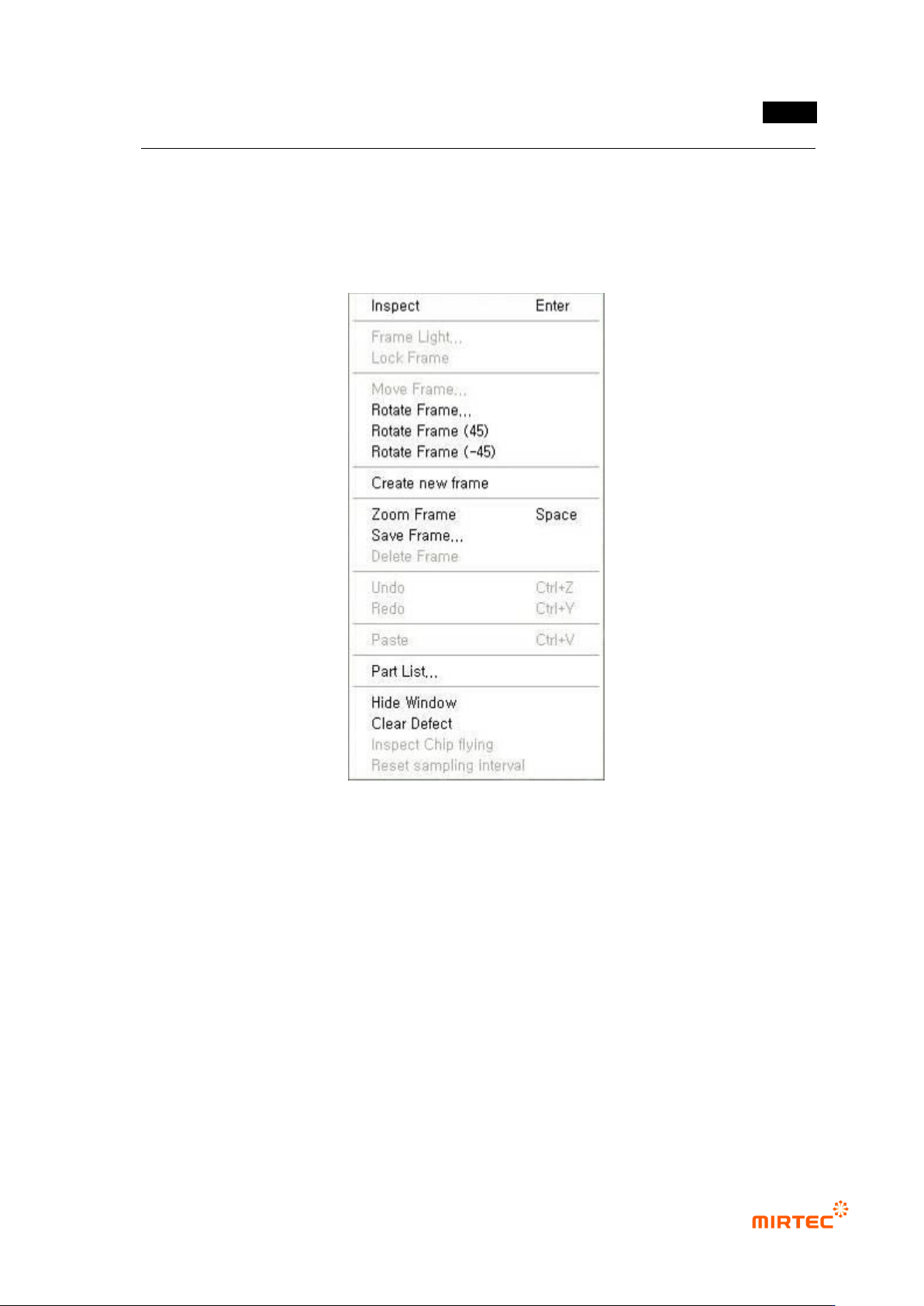
5.5.2 Functions in frame image screen
This chapter is about popup menu that can be used in frame image screen displayed by clicking
right button of the mouse.
[Figure 5-310 frame setting related function]
Inspection
Use this function to inspect only inspection window in the current frame. This is useful to find
correct parameter setting value of the relevant inspection window during teaching. inspection
result will be displayed in the status screen, and many inspection windows can be inspected.
Conduct inspection for component and frame.
Frame light
Use this function to set user light value effective only in the currently selected frame. In
general, inspect component of which body is dark like transistor in the relevant frame or select
light value that is different from light value set at the relevant PCB model for optical character
recognition.
MV-9 User Manual
5-238
[Figure 5-311 user light setting for character recognition]
Flipped component inspection: Inspection of foreign material component besides window
that completed teaching in frame
Fixed frame
In case of „frame auto creation‟ of frame set as fixed frame, the frame is fixed and has no effect.
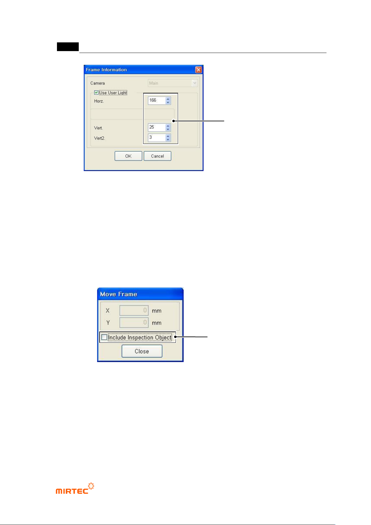
Frame move
Move position of already created frame and add new inspection window to this. In case of
occurrence of interval difference between inspection window and component, use this function
to compensate this.
[Figure 5-312 frame move]
If „Include inspection object‟ is not selected, move frame after fixing inspection window
Inspection window in the frame will be fixed and only the position of the relevant frame will
move. This is used to add a new inspection window in the relevant frame.
Frame move area is limited to the range that includes already created inspection window.
Whether to include inspection
window movement inside frame
when moving
Set User Light to be used in
Only Relevant Frame