MV-9_Chapter 5. Teaching.pdf - 第45页
错误 ! 使用“开始” 选项卡将 제목 2 应用于要在此处显示的文字。 错误 ! 使用“开始”选项卡将 제목 2 应用 于要在此处显示的 文字。 . 5- 45 ② Parameter of non-moun ting inspe ction (moun ting) window - N on -m ounti ng inspection ( m ounti n g) Th i s is used to detect non-m o…
MV-9 User Manual
5-44
3) Non-mounting inspection (mounting)
This is to judge whether there is electrode or not using color information of components of chip
type mounted at mounting end to conduct non-mounting inspection.
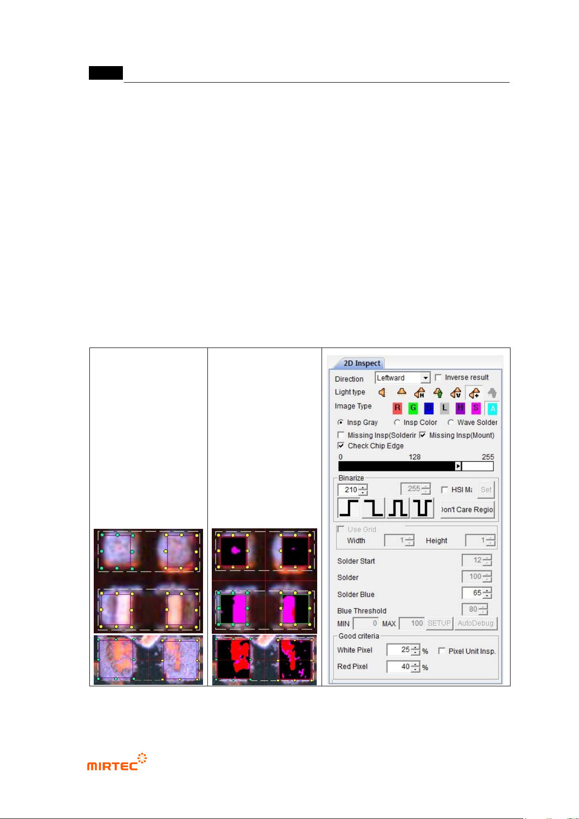
① Teaching method
(a) Draw solder inspection window including solder area and chip electrode and select
direction.
(b) Select horizontal + vertical light for light type. Basically, „A‟ will be automatically selected
for image type.
(c) Click non-mounting inspection (mounting) in parameter window, and select chip
electrode check.
(d) Adjust binarization value and solder blue ratio to separate electrode from solder and
substrate into pink.
(e) Enter normal criteria.
[Figure 5-47 Screen to create non-mounting inspection (mounting) window]
错误!使用“开始”选项卡将 제목 2 应用于要在此处显示的文字。错误!使用“开始”选项卡将 제목 2 应用
于要在此处显示的文字。 .
5-45
② Parameter of non-mounting inspection (mounting) window
- Non-mounting inspection (mounting)
This is used to detect non-mounting defect during mounting status inspection at the rear
part of mounting inspection.
- Chip electrode check
This is for defect detection using existence of chip electrode.
- Binarization
Set binarization value of red and blue.
- Solder blue ratio
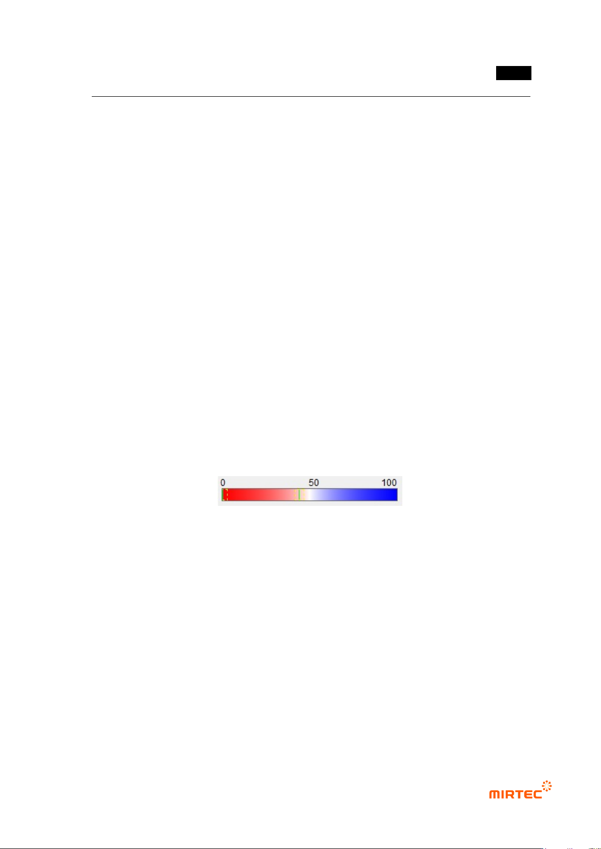
This is to set blue reference of solder. Ratio of blue and red. Based on 50, if it is below
50, it is red series. If it is above 50, it is blue series. Remove solder below reference
value. (The figure below is an example, and it is not displayed in real inspection
window.)
Adjust binarization value and solder blue reference to set electrode area to be displayed
in pink.
If there is stain after mounting and springing of chip, pad is exposed. Not like electrode,
exposed pad is displayed in strong red, and electrode is displayed in low red with low
saturation that is close to white. Therefore, we can tell pad from electrode using solder
blue ratio.
Electrode will be red + white in color light, and solder will be blue, Hence, set it in
approximately 50 ~ 60 range.
- White pixel ratio
Amount of pixel recognized as chip electrode in total window, and it will be pink in
preview screen. If it is below reference setting value, judge as defect.
If non-mounting inspection (mounting) is selected, only red pixel ratio will be activated. If
chip electrode check is selected, white pixel ratio will be additionally activated.
- Red pixel ratio
Ratio of red pixel in solder window. If it is higher than reference setting value, judge as
defect.
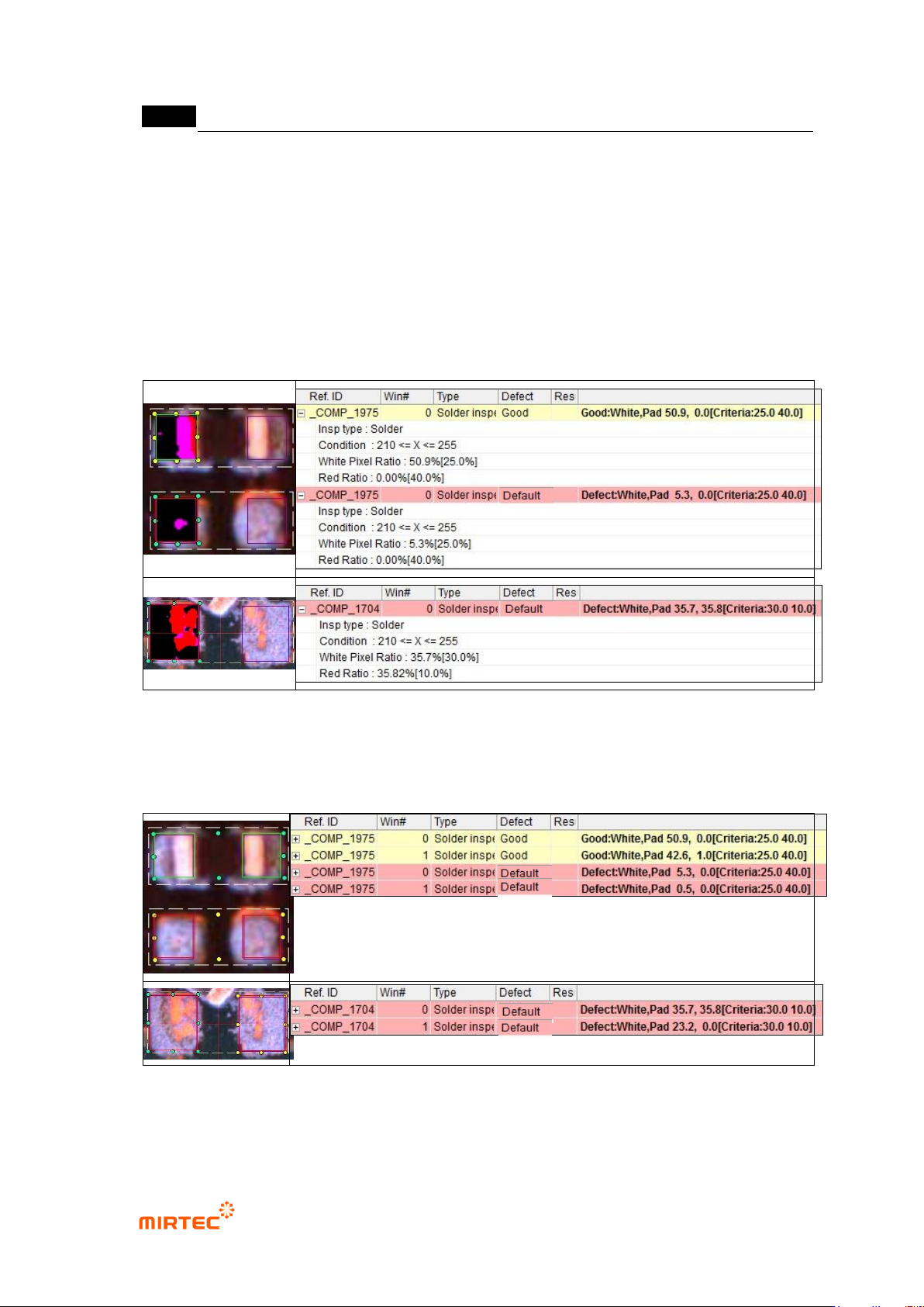
③ Non-mounting inspection (mounting) result in status screen
When chip electrode check is selected
- Inspection Type: name of inspection window.
MV-9 User Manual
5-46
- Condition: status of binarization setting.
- White Pixel Ratio: ratio of white pixel in inspection window. It means ratio of pixel relevant
to electrode.
- Red Ratio: ratio of red pixel in inspection window. It means ratio of pixel relevant to
exposed pad.
- Non-mounting defect at which chip is not mounted and non-mounting defect at which is
mounted but sprang off can be detected while checking ion chip polar star check.
[Figure 5-48 Non-mounting inspection (mounting) in status screen –result when chip inspection
check is selected]
[Figure 5-49 Non-mounting inspection (mounting) –result example when chip inspection check is
selected]
When chip electrode check is selected