MV-9_Chapter 5. Teaching.pdf - 第221页
错误 ! 使用“开始” 选项卡将 제목 2 应用于要在此处显示的文字。 错误 ! 使用“开始”选项卡将 제목 2 应用 于要在此处显示的 文字。 . 5- 221 Frame auto c reation Even for a sam e PCB, the number of total fram es created a f ter teaching can dif fer f rom user ‟s teaching p rof…
MV-9 User Manual
5-220
5.5 Additional teaching function
5.5.1 Functions in whole PCB image screen
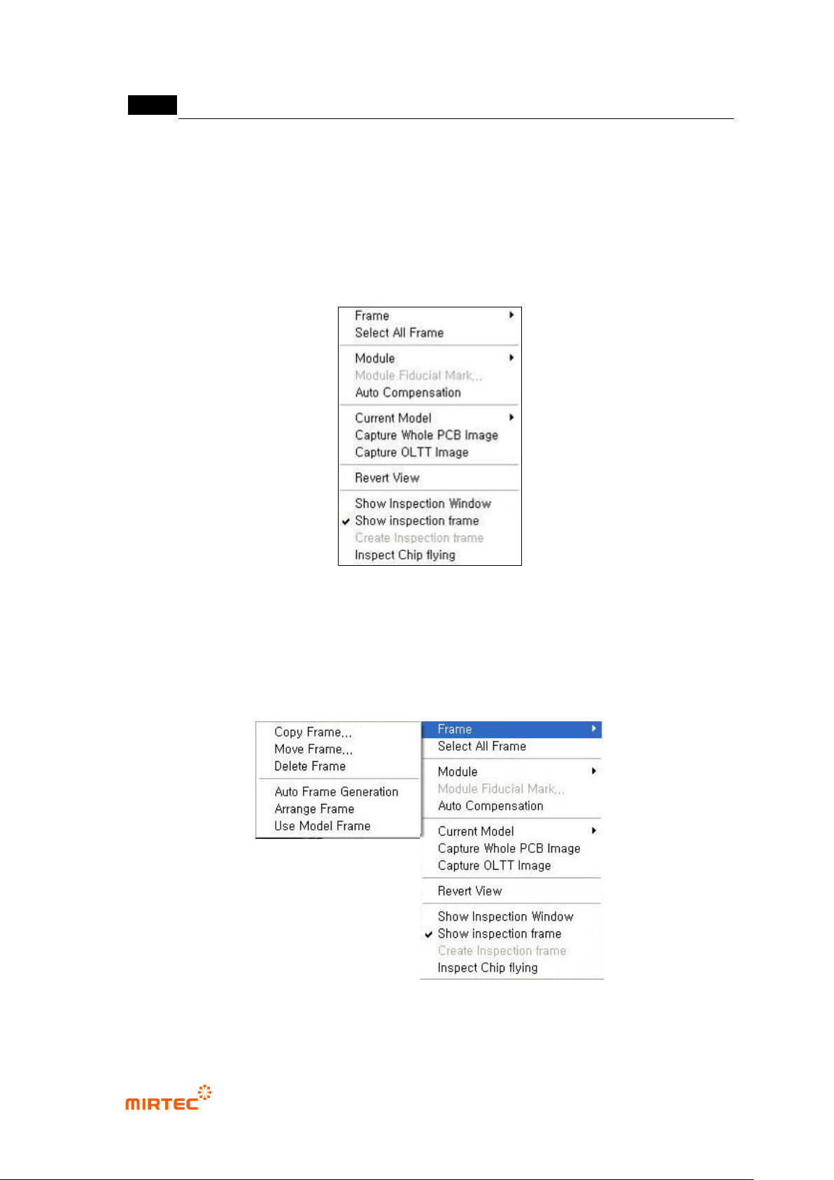
In this chapter we describe about popup menu displayed by clicking right button of the mouse
that can be used in whole image screen.
[Figure 5-280 frame related function menu_1]
5) Frame related functions
This is about the functions like create, copy and move of frame in PCB model that completed
teaching. Clear normal frame image is achieved by imaging every time of frame change.
[Figure 5-281 Frame related function menu_2]
错误!使用“开始”选项卡将 제목 2 应用于要在此处显示的文字。错误!使用“开始”选项卡将 제목 2 应用
于要在此处显示的文字。 .
5-221
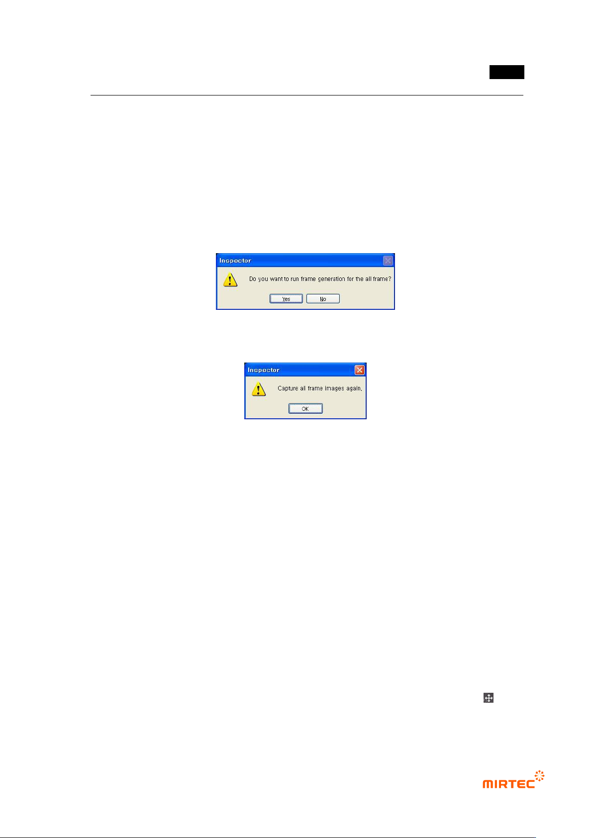
Frame auto creation
Even for a same PCB, the number of total frames created after teaching can differ from user‟s
teaching proficiency. Added to that, number of total frames is closely connected to inspection
time. this is optimization function to re-create frame to include max inspection windows per 1
frame for the target of inspection windows that completed teaching regardless of user‟s
teaching proficiency. The number of total frames and inspection time can be reduced using
this function.
Click frame auto creation button to display the screen below. Click <Yes (Y)> button to display
frame image re-image message and click <No (N)> button to cancel it.
[Figure 5-282 frame auto creation check]
[Figure 5-283 frame image re-image]
Re-image frame image when re-image is started, and it moves to the position of each frame to
be created to re-adjust position of each window using pattern matching method.
Frame arrange
In case of copy, move or delete in frame, apply this to the frame.
Frame copy
This function is to copy frame selected in whole image screen. Basically, newly created frame
is located on the right side of the selected frame, and it will be set into frame move status as
soon as it is copied. At this point, user can move the frame that is copied to desired position.
(many frames can be copied at a same time.)
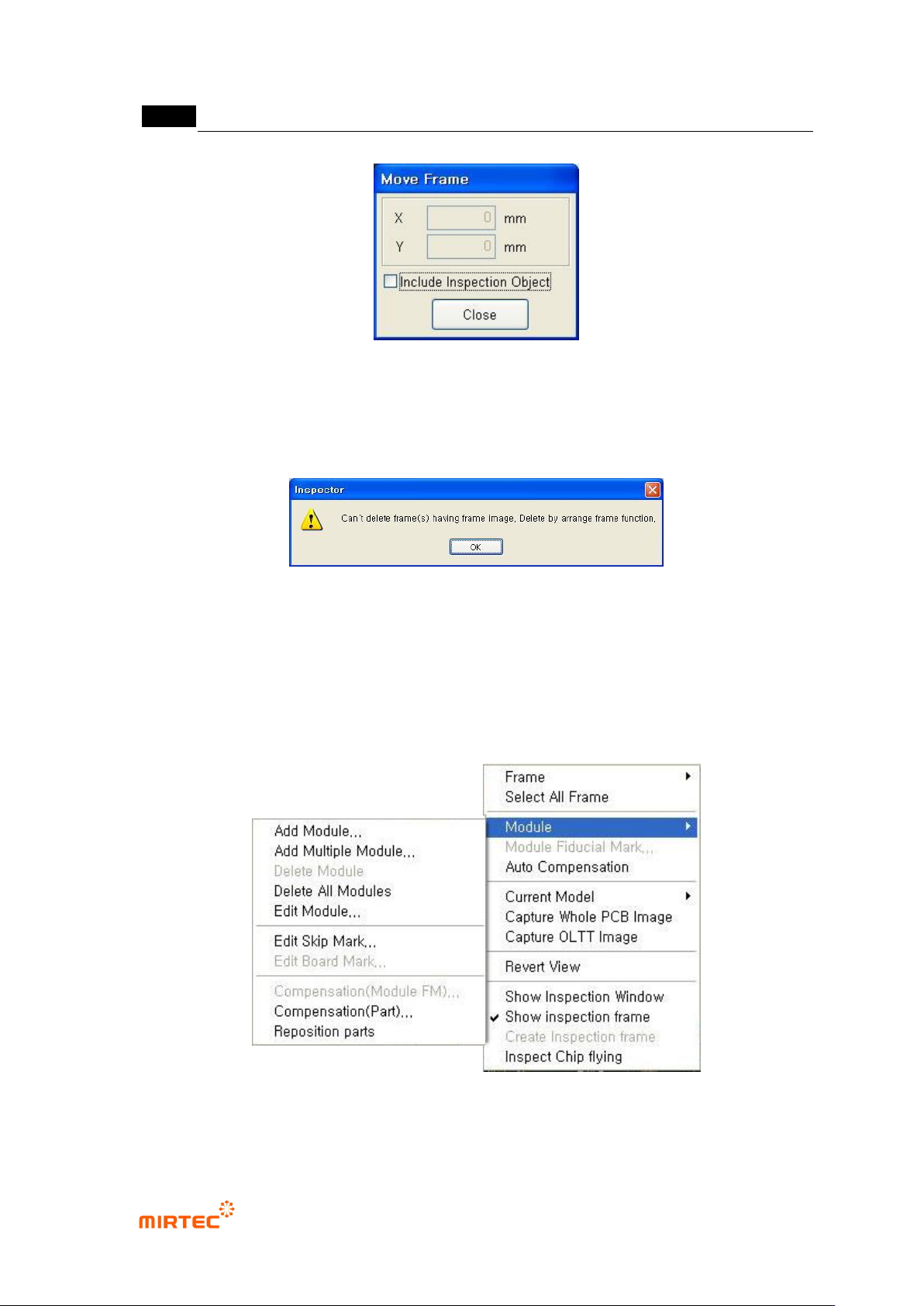
Frame move
This function is used to adjust position of the selected frame. At this point, going inspection
windows which are already included out of the frame is limited. Added to that, if „Include
inspection object‟ option is selected, separation between inspection window and real
inspection target component can be adjusted. (many frames can be moved at a same time.)
Firstly, select „frame move‟ menu, and when mouse cursor is changed to cross shape (
display) move the frame to desired position in frame image screen while pressing the left
button of mouse.
MV-9 User Manual
5-222
[Figure 5-284 frame move]
Frame delete
This function is to delete a selected frame. After deleting frame, end frame delete using frame
arrangement function in the screen below.
[Figure 5-285 frame delete end screen]
6) Module related function
If there are many modules on 1 PCB, the following functions are used to add, delete and edit
module. The following is module popup menu and PCB hierarchy structure during model
teaching.
[Figure 5-286 module menu]