MV-9_Chapter 5. Teaching.pdf - 第131页
错误 ! 使用“开始” 选项卡将 제목 2 应用于要在此处显示的文字。 错误 ! 使用“开始”选项卡将 제목 2 应用 于要在此处显示的 文字。 . 5- 131 Judge m in or m ax color r atio of red and blue to color of lead par t. In case o ccurrenc e of li fted l ead , detect li f ted defect…
MV-9 User Manual
5-130
Common parameter: binarization
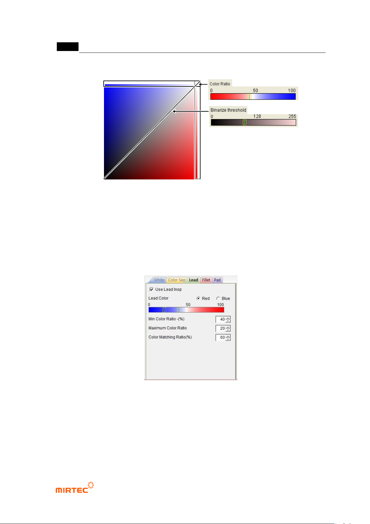
[Figure 5-145 RB color plane and binarization parameter]
- Color ratio
Display color of axis of which blue (Blue) is 255 or red (Red) is 255 at RB color plane.
- Binarization boundary value
Display all colors of axis relevant to color ratio in RB color plane.
Lead parameter
[Figure 5-146 solder amount inspection setting_lead]
- Use lead inspection
This option is to set whether to use lead part inspection
- Lead color
This option is to judge color of lead part
- Min color ratio - (%) and max color ratio + (%)
RB Color Plane
Red
Blue
错误!使用“开始”选项卡将 제목 2 应用于要在此处显示的文字。错误!使用“开始”选项卡将 제목 2 应用
于要在此处显示的文字。 .
5-131
Judge min or max color ratio of red and blue to color of lead part.
In case occurrence of lifted lead, detect lifted defect using the characteristic of which
color of lead color inspection area different from normal.
If each lead color exceeds min color ratio and max color ratio to average based on
average color of all lead, judge as defect. For example, if average color of 4 lead is 50,
the following is normal range calculation, and lead color normal range is 40 ~ 50.
Min = 50 – 50ⅹ40% = 30, max = 50 + 50ⅹ20% = 60
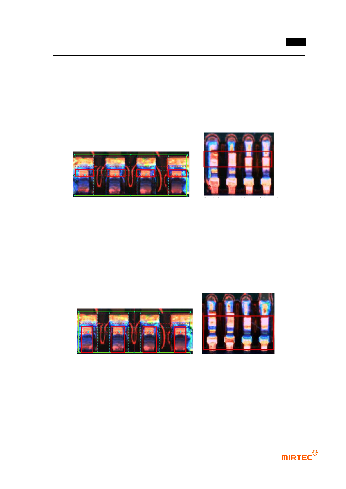
[Figure 5-147 lead color inspection area and defect example]
- Color matching ratio (%)
Color matching ratio means matching ratio of each lead to created reference model
after reference model of all lead color distribution for inspection area.
In case of occurrence of lifted lead, color matching ratio detects lifted defect using the
characteristic of which color distribution in area from lead shoulder to lead tip different
from normal.
In case matching ratio of each lead is below setting value, judge as defect. min
matching ratio = 0%, max matching ratio = 100%.
[Figure 5-148 lead color matching ratio inspection area and defect example]
MV-9 User Manual
5-132
Fillet parameter
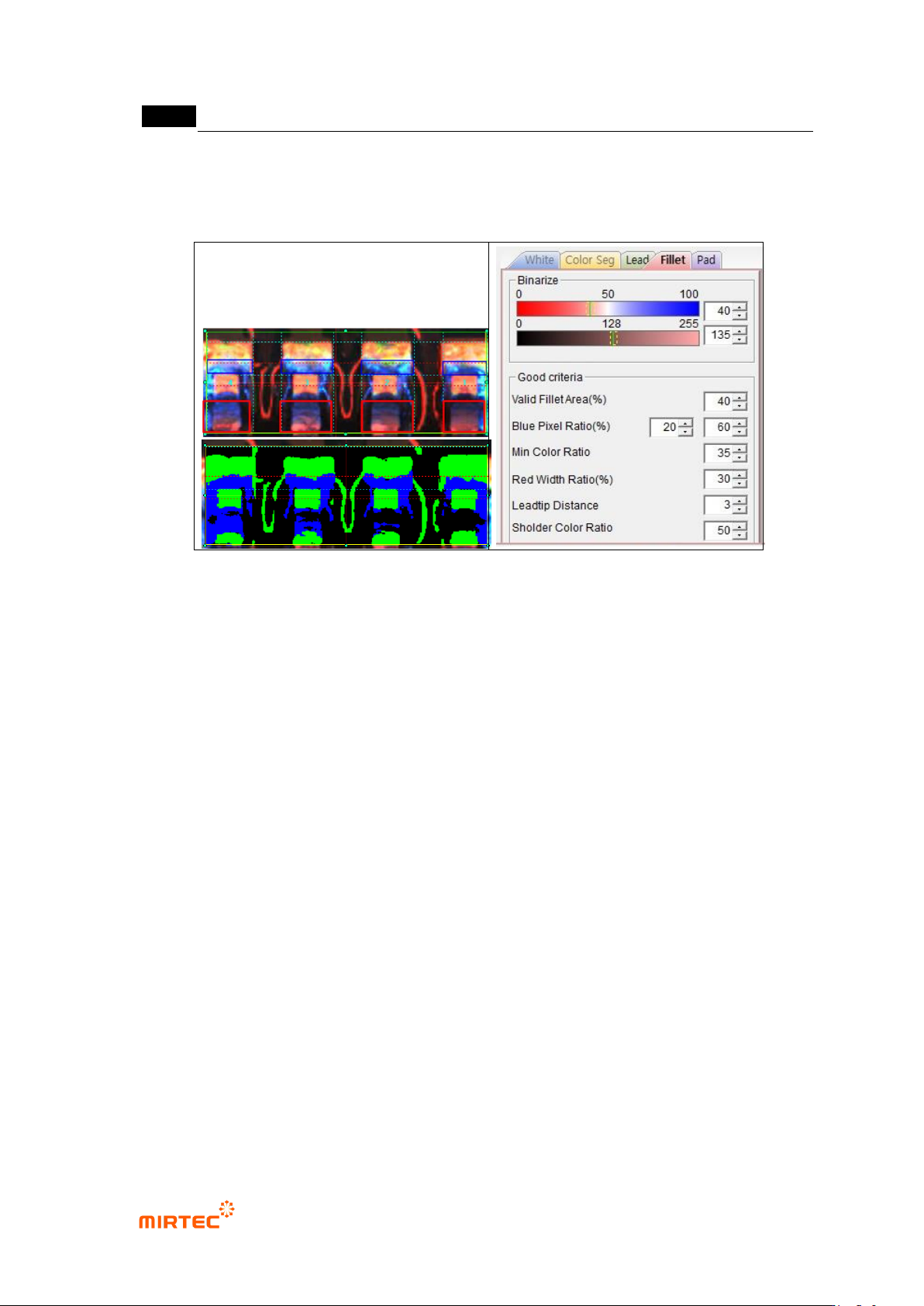
[Figure 5-149 solder amount inspection setting_fillet and preview image]
- Binarization
Use color ratio and binarization boundary value for binarization.
Color ratio: set ratio of blue to red of fillet area. Pixel of which color ratio is above
reference value will be displayed in blue, and pixel of which color ratio is below
reference value will be displayed in green.
Binarization boundary value: pixel of which red and blue value is below binarization
value will be all „0‟ (black).
- Normal criteria
Effective fillet area (%): set ratio of pixel that is above binarization boundary value for
total fillet area (black is excluded). detect some of insufficient solder/no solder and lifted.
If it is below reference value, judge as defect.
Blue pixel ratio (%): set ratio of blue pixel to fillet area. If it is above min value (Ex: 20%),
it is defect. If it is above max value (Ex: 60%), it is normal. If it is between min value and
max value, the 2
nd
judgment will be made by using other setting values.
Min color ratio: set color ratio of blue in fillet area. Detect some of insufficient solder/no
solder and lifted. If it is below reference value, judge as defect.
Red pixel thickness (%): thickness of red pixel (green in preview image) of pad. If lifted
lead occurs, detect defect using the characteristic of which red area of pad area
narrows.
Lead tip distance: distance between position of each lead tip and average lead tip
position of total lead. If it is above reference value, judge as defect. In case lifted lead