MV-9_Chapter 5. Teaching.pdf - 第274页
MV -9 Use r Manual 5- 274 46 Register ID of markers on the 3D BLU inspect i on window . 47 Sel ect „Edit Part‟ mode. 48 Select the m ounti ng inspection window for 3D BLU. 49 If the 1st ID (the 2nd ID or 3rd ID) is c li …
错误!使用“开始”选项卡将 제목 2 应用于要在此处显示的文字。错误!使用“开始”选项卡将 제목 2 应用
于要在此处显示的文字。 .
5-273
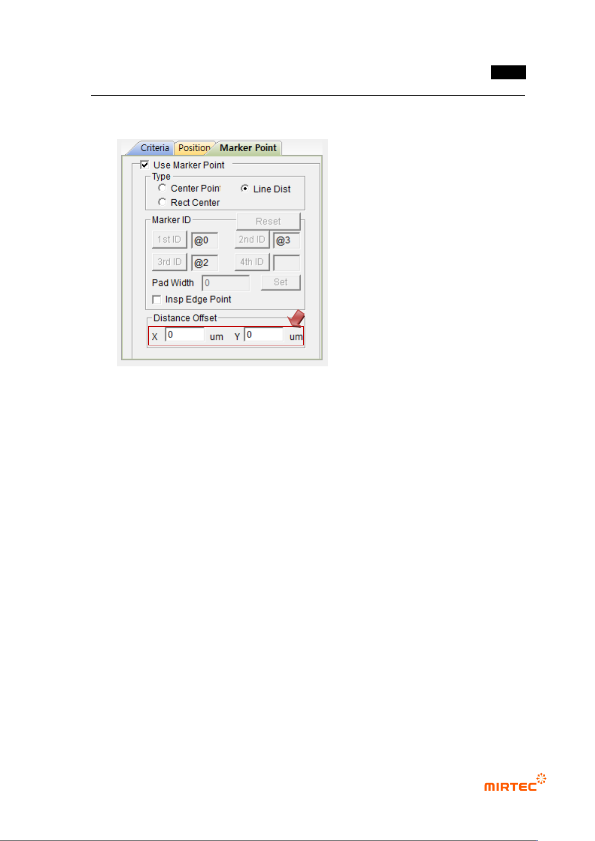
45 Set Distance Offset
- In case of Center Point: Set X, Y Offsets on the basis of the Center Points of markers.
- In case of Line Dist.: Set X and Y Offsets on the basis of the first marker.
- In case BLU is not located at the center of BLU Bar or in case the markers are
misplaced, it is possible to adjust the reference values for Center Point of BLU to be
inspected by using X and Y Offsets.
MV-9 User Manual
5-274
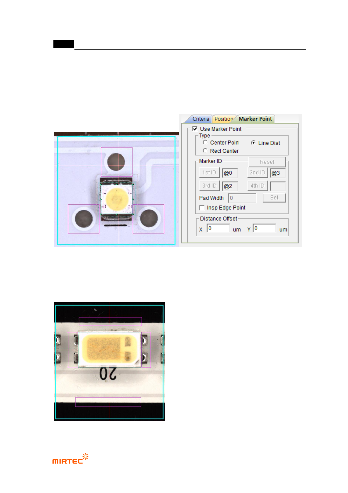
46 Register ID of markers on the 3D BLU inspection window.
47 Select „Edit Part‟ mode.
48 Select the mounting inspection window for 3D BLU.
49 If the 1st ID (the 2nd ID or 3rd ID) is clicked from maker ID‟s and the previous inspection
window is selected, the marker ID is registered.
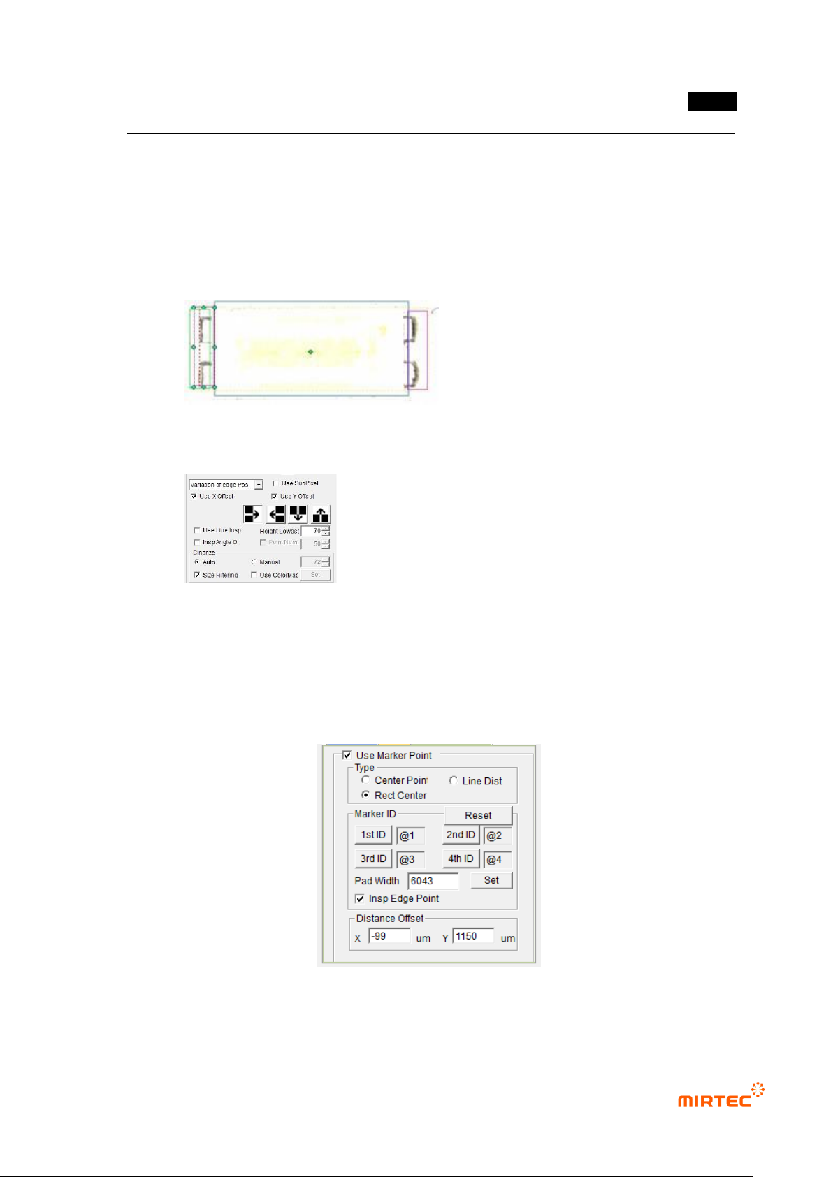
5.9.9 Teaching Method in case of No Markers (Use RectCenter)
① After drawing the inspection window for position move at the top, the bottom and both
pad ends, as shown in the following figure, tie the parts.
错误!使用“开始”选项卡将 제목 2 应用于要在此处显示的文字。错误!使用“开始”选项卡将 제목 2 应用
于要在此处显示的文字。 .
5-275
② After executing „Edit Parts‟ mode, set the parameters of each window.
③ Check the angle inspection for the windows drawn up/downward and do not check the
angle inspection for the windows drawn at both ends of the pad.
④ For the windows drawn at both ends of the pad, strengthen the vertical lighting by using
users‟ lighting in order to minimize the solder effect.
⑤ The parameter setting of the window at the ends of the pad is as follows:
⑥ Set the marker point in the order of top, bottom, left and right. Since the inspection is
made in the order of LED markers, it is impossible to conduct the inspection in case the
position of 1/2 and the position of 3/4 are changed to each other.
⑦ The parameters set for markers are as follows:
⑧ Input „Pad Width‟. If „Set‟ button is pressed, it is set automatically..
⑨ The Pad Width should be set to inspect the Shift on the basis of one pad in case LED