MV-9_Chapter 5. Teaching.pdf - 第33页
错误 ! 使用“开始” 选项卡将 제목 2 应用于要在此处显示的文字。 错误 ! 使用“开始”选项卡将 제목 2 应用 于要在此处显示的 文字。 . 5-33 Use max matching ratio - This is to conduct pattern m atchi ng of all register ed patt er n im ages . Comp are the hi g hest m atchi ng ra…
MV-9 User Manual
5-32
Binarization
Manually set binarization value for more correct recognition after auto binarization of
character image. Select pattern model desired to be manually set to set binarization value.
Teaching method
i. Select mounting inspection algorithm and draw mounting image.
ii. Set character emphasis option.
[Figure 5-31 Before noise removal]
[Figure 5-32 After noise removal]
[Figure 5-33 Filter size - 1]
[Figure 5-34 Filter size - 2]
iii. As shown in [Figure5-48], in case there is noise besides character part, set noise
removal parameter to remove noise as shown in [Figure5-49].
iv. As shown in [Figure5-50], in case there is noise on image of character part itself,
set filter size to remove noise as shown in [Figure5-51].
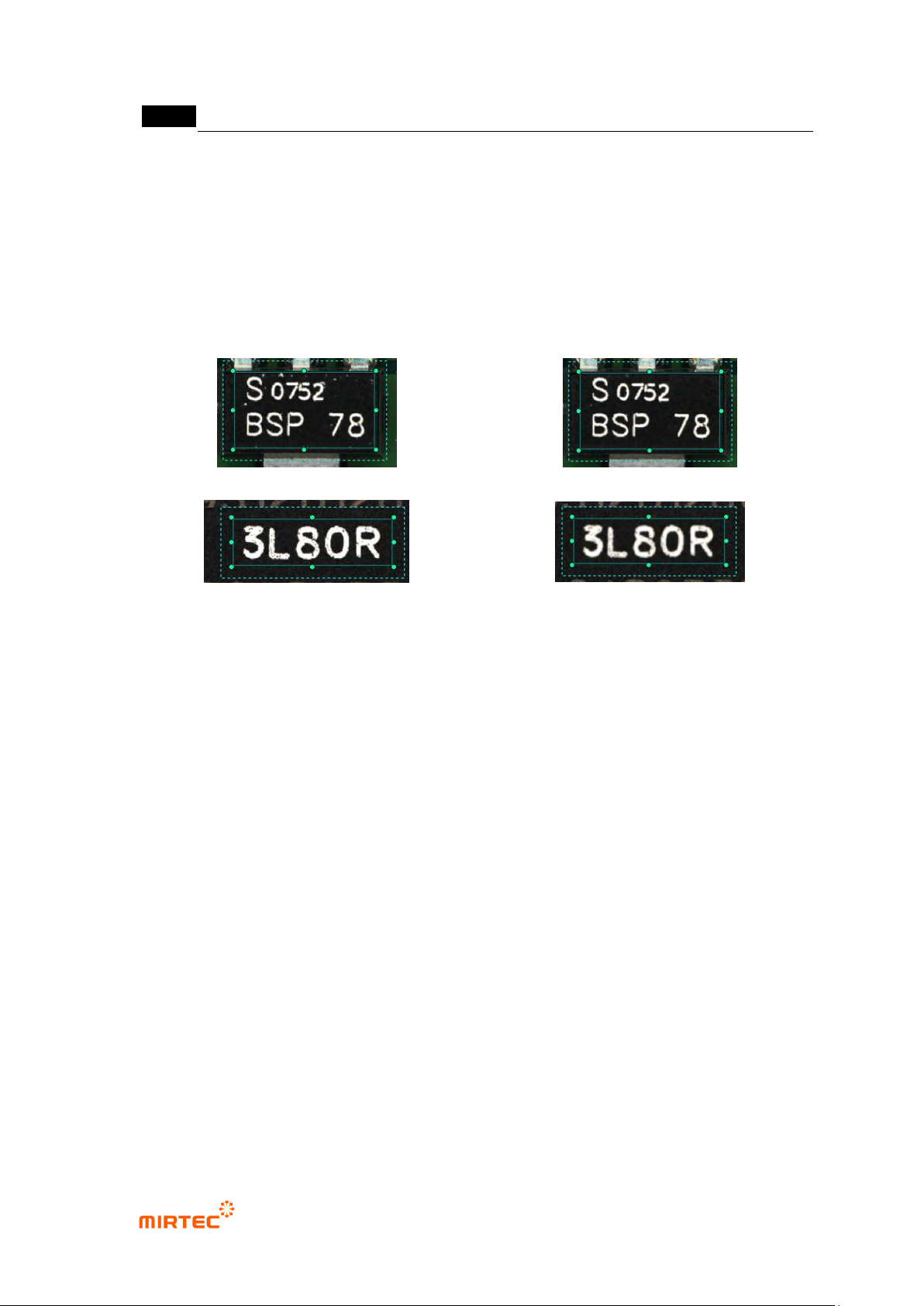
v. In case of C chip or R chip, teaching must be done only for character part through
component edit mode.
Matching ratio
- Reference value judge inspection result value during PCB inspection. If it is lower than
reference, judge as defect and if it is higher than reference, judge as good.
Sensitivity
- Mainly, adjust sensitivity of mounting inspection for character inspection not to judge defect
component as normal according to fine sensitivity change of a component. It will be
activated when inspection type is normal mounting. Sensitivity can be set to max 3 stages.
Equally segment inspection area into the select region, and calculate each matching ratio.
Extract max matching ratio to compare it with reference matching ratio for good/defect
judgment.
Ignore deleted character
- This option is valid only when sensitivity is set to 3 regions. If more than 2 regions are
higher than reference matching ratio among 3 segmentation regions, judge as good.
-
错误!使用“开始”选项卡将 제목 2 应用于要在此处显示的文字。错误!使用“开始”选项卡将 제목 2 应用
于要在此处显示的文字。 .
5-33
Use max matching ratio
- This is to conduct pattern matching of all registered pattern images. Compare the highest
matching ratio with reference value to judge good/defect.
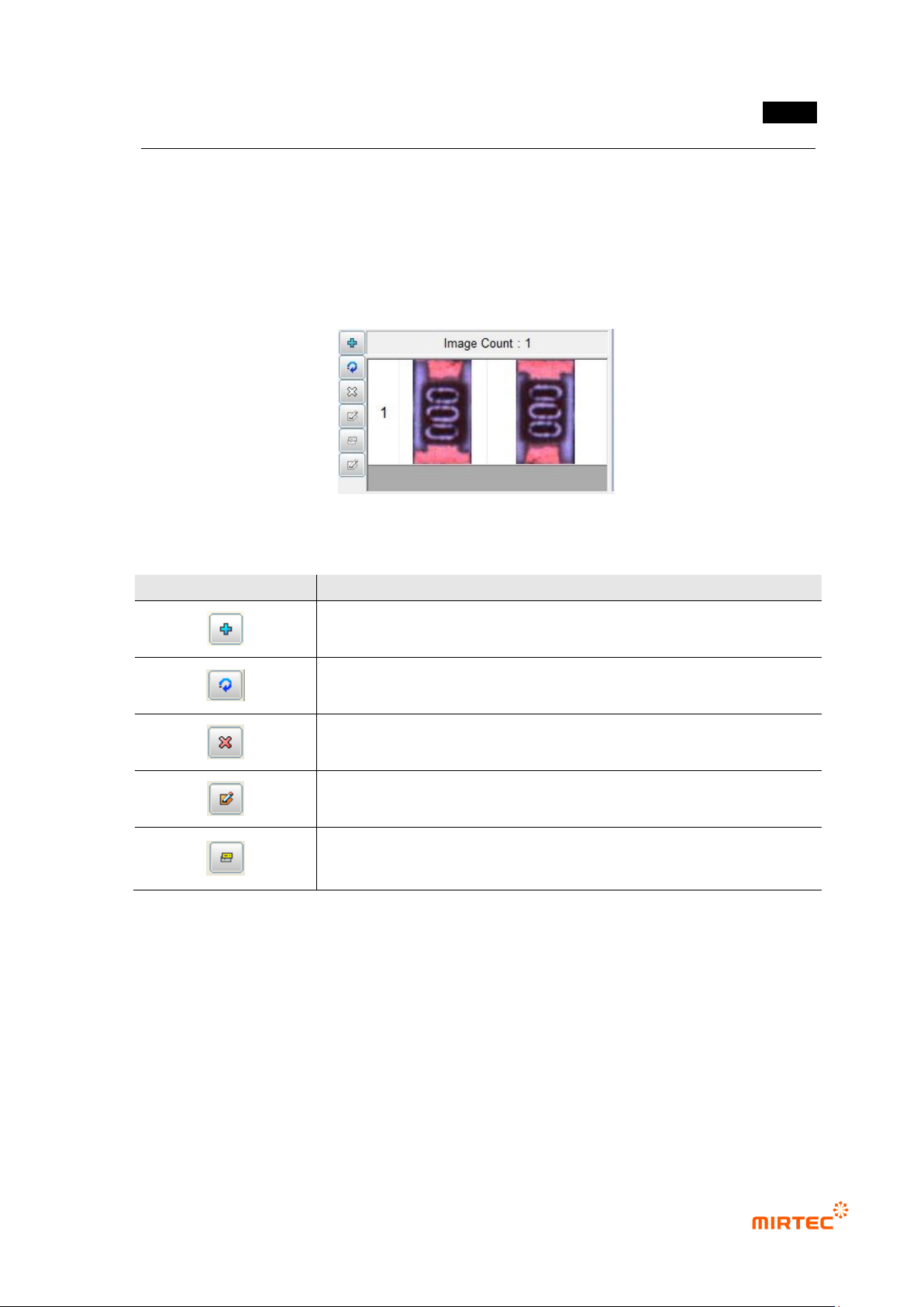
Pattern image screen
- This screen is to display pattern image registered during mounting inspection and chip
inspection.
[Figure 5-35 Pattern image screen]
[Table 5-2 Description of operating buttons]
icon
Name and Description
Current image add: add current image.
Current image refresh: re-image current image.
Current image delete: delete current image.
Mask image edit („Don‟t care region‟ setting): set unnecessary image
region to skip it during inspection.
Image synchronization: select specific pattern image and click
synchronization button to set „Don‟t care region‟ of a specific pattern at
once.
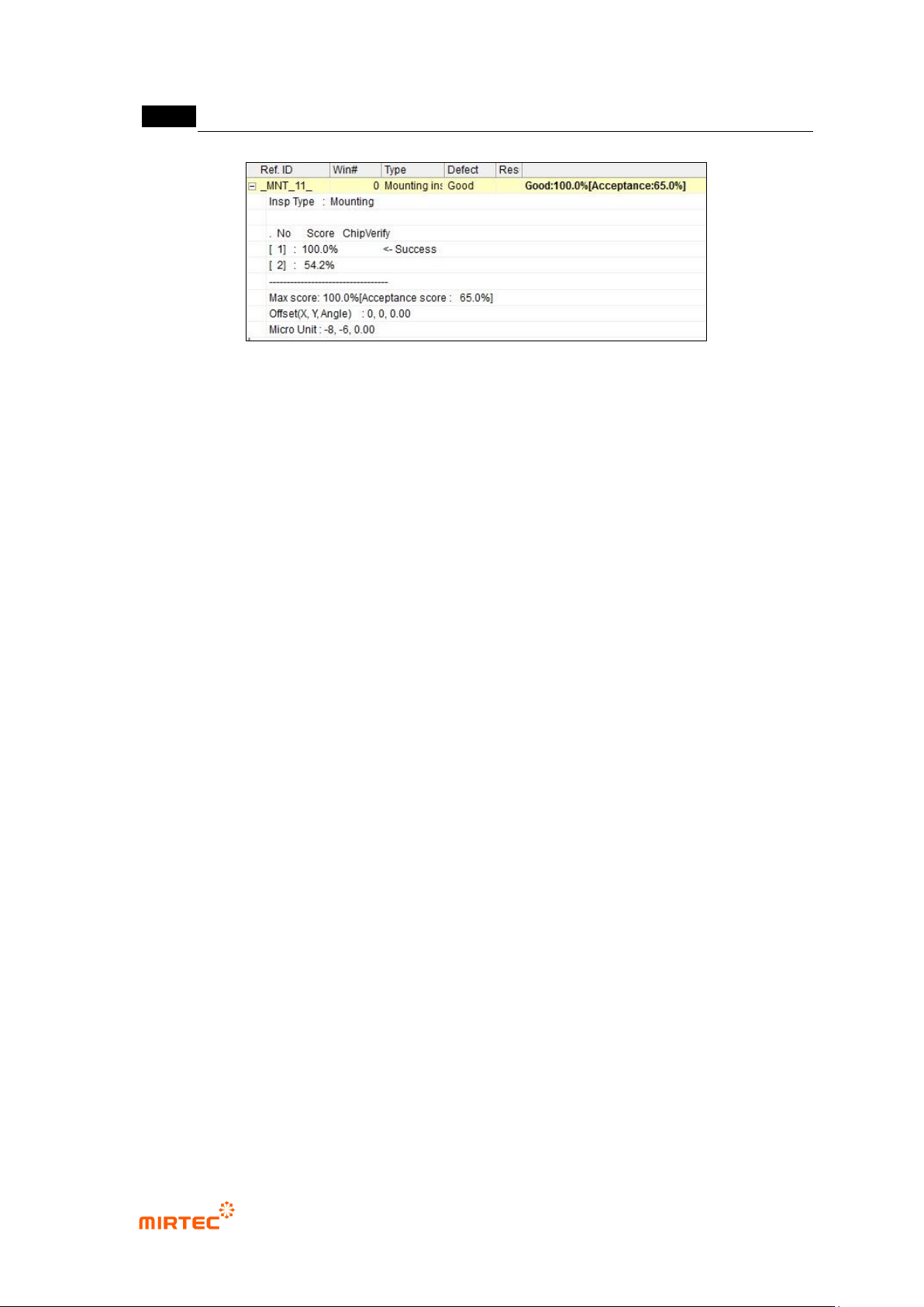
4) Inspection result in status screen
- To directly inspect mounting inspection window that completed teaching, select inspection
window and select „Inspect‟ in popup menu displayed by clicking right button of the mouse
or press enter key to start inspection. The following inspection result will be displayed in
inspection result screen on the bottom of the main screen after inspection.
MV-9 User Manual
5-34
[Figure 5-36 mounting inspection window inspection result screen]
Shape
- This is to display inspection type (inspection algorithm).
Defect name
- This is to display inspection result and item selected at good/defect type.
No
- Number in square bracket means the order of registered pattern image for the relevant
component. If polarity is not set among inspection options, images rotated for one sub
image will be inspected at the same time. Hence, there will be 2 models.
Matching ratio
- The value displayed in percent is matching ratio between image registered in pattern
image screen and imaged image.
Chip re-inspection
- Chip re-inspection result will be judged and displayed by „O/X‟.
Success
- This will be displayed for a model that successfully completed matching among registered
many models.
Max matching ratio
- This is to display max matching ratio among the registered models. Percent in brace
means normal judgment matching score.
Offset (x, y)
- This is to display offset value from the center of inspection window to the center of
component found in search area in pixel unit.