MV-9_Chapter 5. Teaching.pdf - 第58页
MV -9 Use r Manual 5- 58 [Figure 5- 62 Wave sol dering inspection teaching and preview] Norm al image Solderi ng inspection teaching window Color inspection teachi n g windo w [Figure 5- 63 perforation inspection teachin…
错误!使用“开始”选项卡将 제목 2 应用于要在此处显示的文字。错误!使用“开始”选项卡将 제목 2 应用
于要在此处显示的文字。 .
5-57
3) Parameter of Wave Solder inspection window
Reference name
- Refer to „reference name (page) ' in „5.3.1
- ‟ excepting shape.
- Created in „_SLD_1_‟ format. At this point, „SLD‟ means Solder and the number means the
creation order of solder amount inspection window.
Component name
- Refer to „component name (page)‟ in „5.3.1 Light type
- Select horizontal + vertical light for wave soldering inspection.
Image type
- Select „A‟ for image type.
Inspection type
- Select wave solder among 3 soldering inspection types.
Component type
- Component type is divided into pin type and lead type according to component. Especially,
in case of pin type, component with one pin is out and component with many pins out. In
case of the second, select Multi Pin Type.
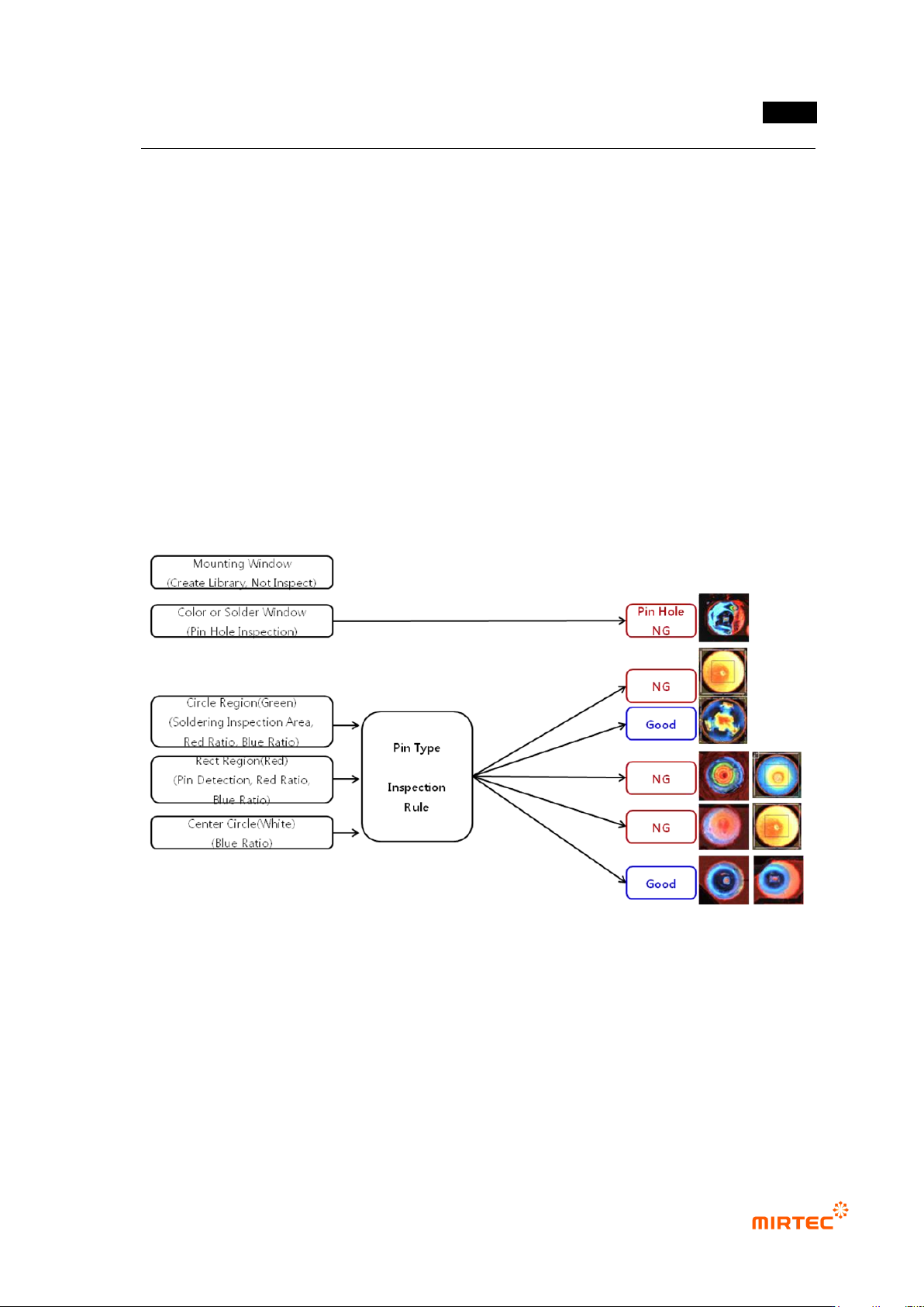
Circle Region
- Designate position and radius of green circle for soldering inspection.
Rect Region
- Designate position of red rectangle and size of width and height to inspect pin lead
exposure.
Good Criteria
- All Blue Ratio (%): blue ratio in green circle area
- All Red Ratio (%): red ratio in green circle area
- Pin Red Ratio (%): red ratio in red rectangle area
- Width / Height Ratio (%): width height width ratio of red area in green circle area
- Center Blue Ratio (%):blue ratio in white circle area
MV-9 User Manual
5-58
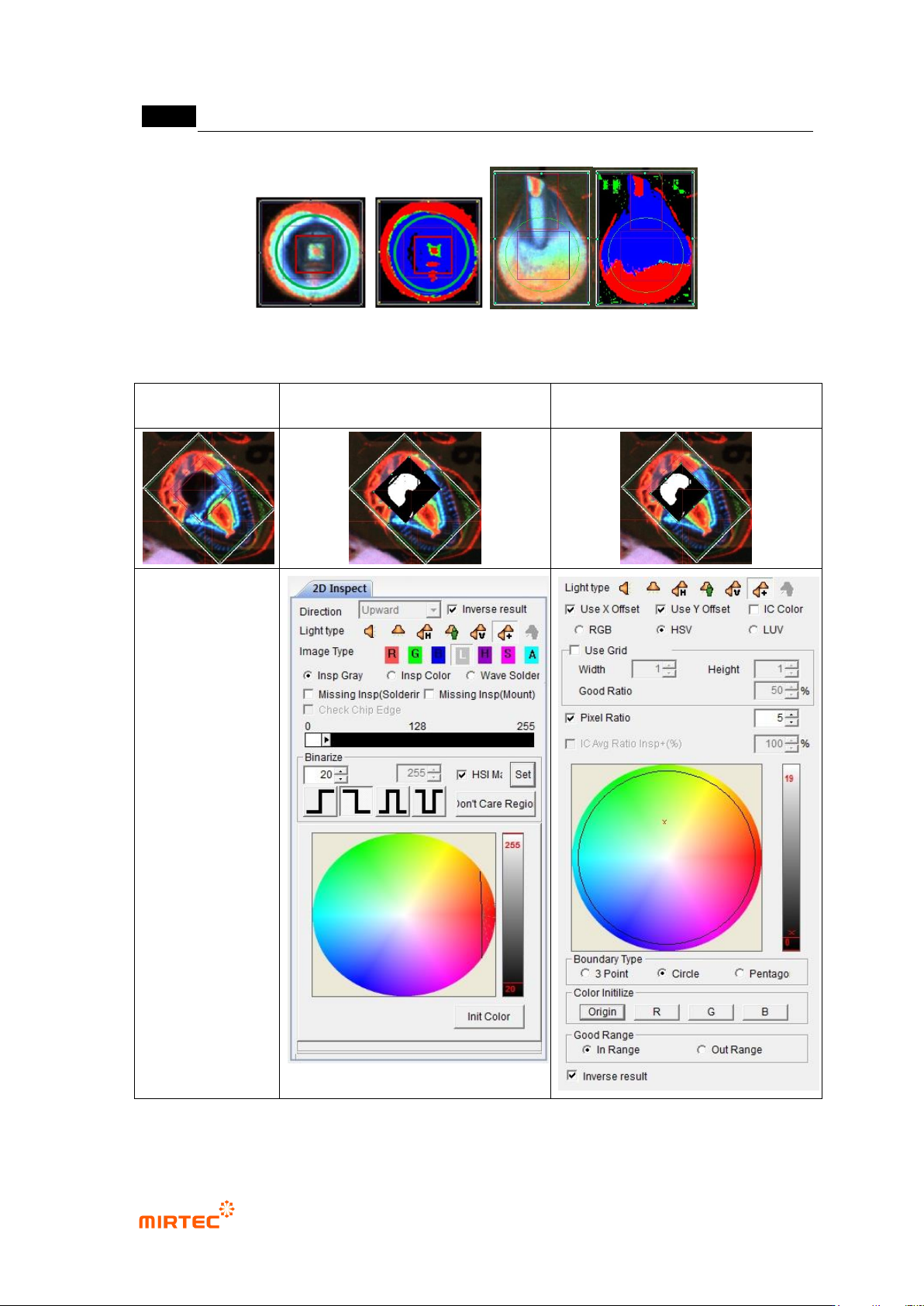
[Figure 5-62 Wave soldering inspection teaching and preview]
Normal image
Soldering inspection teaching
window
Color inspection teaching window
[Figure 5-63 perforation inspection teaching and preview]
错误!使用“开始”选项卡将 제목 2 应用于要在此处显示的文字。错误!使用“开始”选项卡将 제목 2 应用
于要在此处显示的文字。 .
5-59
4) Good/defect judgment rule
- Soldering shape of pin type is almost similar, and most of pin exposure can be clearly
recognized. However, soldering shapes of lead type are very various according to lead
amount, and many times image does not displayed according to bending angle of lead
even in normal soldering status. Hence, use a lot of information for more correct inspection
and good/defect judgment.
Pin type inspection sequence
Perforation inspection will be independently conducted in color inspection window.
For multi-pin type, no solder, inspect insufficient solder, excessive solder defect using
blue ratio in soldering inspection area and red ratio in pin (lead) inspection area.
For pin type, inspect no solder, insufficient solder, excessive solder and no pin exposure
defect using red ratio in pin (lead) inspection area and blue ratio in excessive solder
inspection area according to blue ratio of soldering inspection area.
Lead type inspection sequence
Perforation inspection will be independently conducted in color inspection window.
In case of lead type, if lead is exposed, judge as good. Exposed lead appears in red in
color image. However, in many cases, lead does not appeared in red by bending angle
of lead and lead amount in normal soldering status.
Red ratio in pin (lead) inspection area is larger than reference value. Judge good/defect
using blue ratio and red ratio in soldering inspection area.