MV-9_Chapter 5. Teaching.pdf - 第156页
MV -9 Use r Manual 5- 156 5) Inspection result in st atus scre en - Same with inspection result in status screen of the relevant general-purpose inspection window . 5.3.9 Height inspection wind ow - This is used to measu…
错误!使用“开始”选项卡将 제목 2 应用于要在此处显示的文字。错误!使用“开始”选项卡将 제목 2 应用
于要在此处显示的文字。 .
5-155
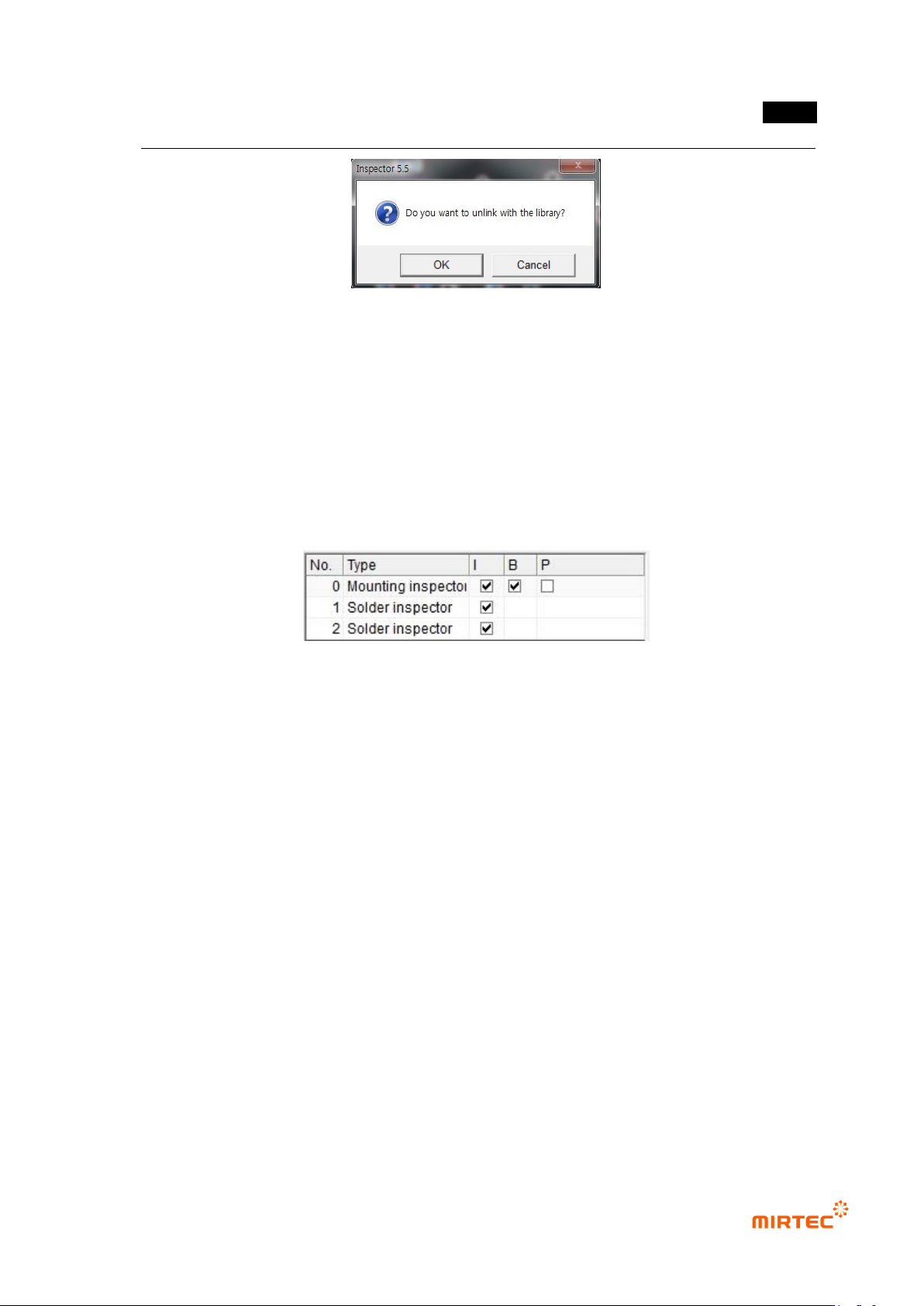
[Figure 5-186 Library unlink of component inspection window]
Inspection window list
- List of general-purpose inspection windows that configure component inspection window.
- In case of mounting inspection window, „compensation window‟ is set as initial value to
equally apply compensation offset of inspection window to solder amount inspection
window. If compensation offset is not used, clear setting.
- Double click general-purpose inspection window item to convert operation status screen
into screen of the relevant inspection window to edit desired parameter.
[Figure 5-187 Grouped inspection window list]
4) Parameter of individual inspection window
Mounting inspection window
- This part is the description of parameter that is newly added for chip component inspection.
For more information about other items, refer to „5.3.1 mouting inspwction window (5-20
page)’.
- Chip re-inspection
This option will be activated only for resistance and capacitor component.
Re-verification that used self algorithm in case of defect occurrence to raise not-
adjusted ratio during chip component inspection. This inspection is used to reduce false
defect ratio.
Setting for chip re-inspection can be done in chip re-inspection of „component inspection
window setting’ in „Config.‟
Judge only the existence of chip during chip re-inspection.
Solder amount inspection window
- Refer to „5.3.1 mounting inspection window (page 5-20)’.
MV-9 User Manual
5-156
5) Inspection result in status screen
- Same with inspection result in status screen of the relevant general-purpose inspection
window.
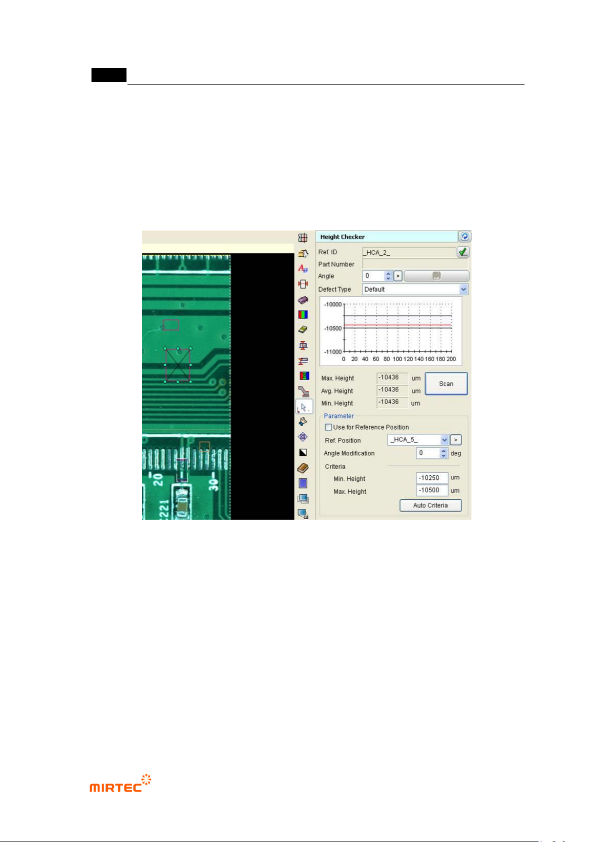
5.3.9 Height inspection window
- This is used to measure lifted defect using component height inspection.
[Figure 5-188 height inspection window setting screen]
Reference name
Refer to „reference name in „5.3.1 mounting inspection window‟ excepting shape.
Name is created in „_HCA_6_‟ format. „HCA‟ means height and the number means creation order
of lifted inspection window.
Component name
Refer to „component name in „5.3.1 mounting inspection window‟.
Rotation angle
This is to set laser rotation angle.
Max/average/min height
Display max peak/average/min value of data from section scanned by laser.
错误!使用“开始”选项卡将 제목 2 应用于要在此处显示的文字。错误!使用“开始”选项卡将 제목 2 应用
于要在此处显示的文字。 .
5-157
Measurement
Collect data from section scanned by laser.
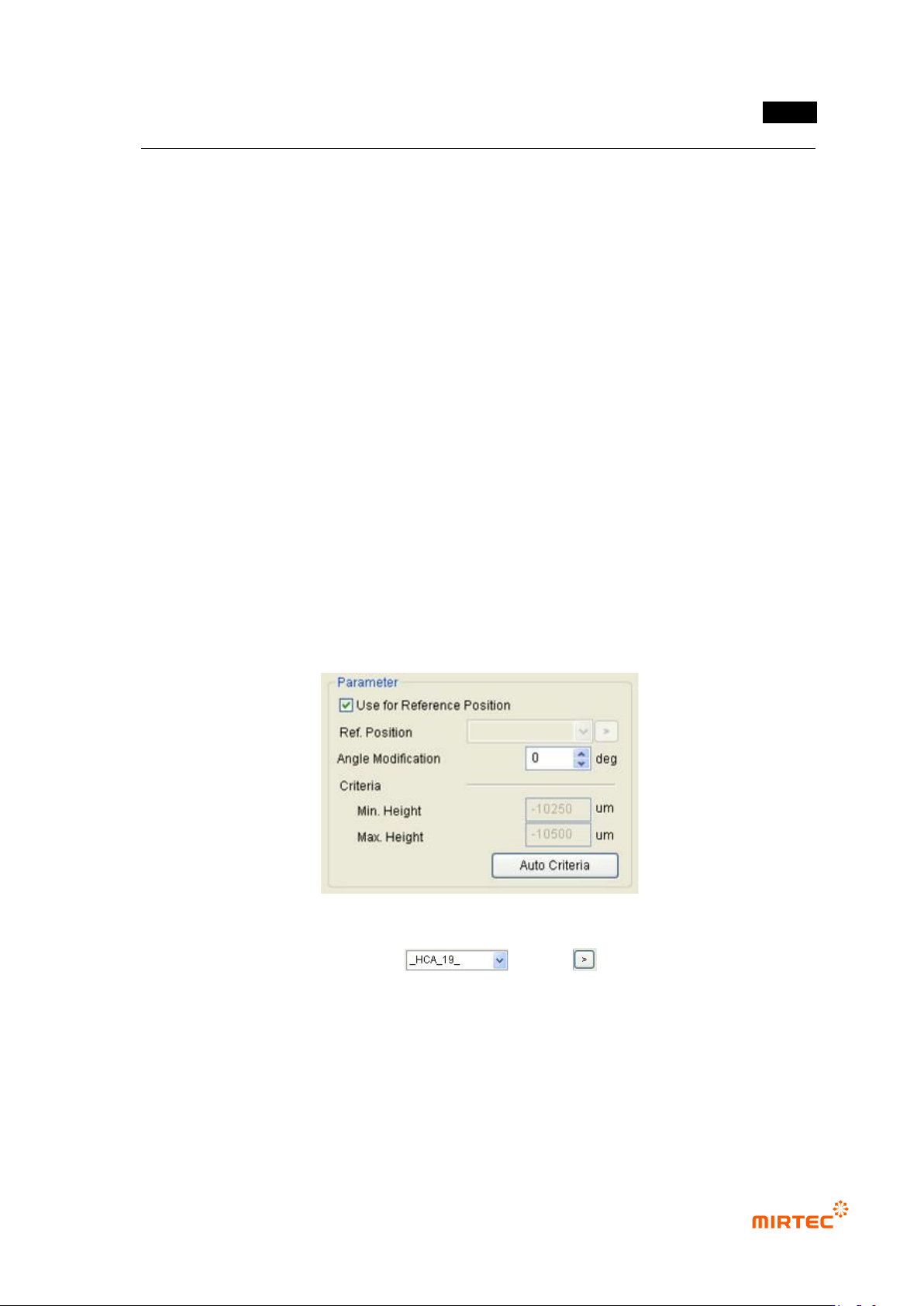
Use as reference position
Set this function to refer to height of other window
Reference position
Enter or click reference name of window to set window to be referred
Angle compensation
Angle compensation is not needed because only height inspection is conducted. However, if
measurement is interrupted by other component, it can be avoided by compensating angle.
Inspection condition
Click „measure‟ to collect data and set proper value.
Teaching method
① Click <height inspection window> button among „operating buttons‟.
② To set reference position (position at which height is considered as „0‟), create „height
inspection window‟ and select „Use reference position‟ to use and set it as reference height
without height measurement.
[Figure 5-189 Height inspection window reference position]
③ Create „height inspection window‟ at position for height measurement and select window
used as reference position in list ( ) or click button and select „Use
reference position window‟.