MV-9_Chapter 5. Teaching.pdf - 第134页
MV -9 Use r Manual 5- 134 Bina rization boundary va l ue : pixel of w hi ch re d and blue va l ue is below bi narizat io n value will be all „0‟ (black). - Ignore p ad area inspection Set w hethe r to inspection for …
错误!使用“开始”选项卡将 제목 2 应用于要在此处显示的文字。错误!使用“开始”选项卡将 제목 2 应用
于要在此处显示的文字。 .
5-133
occurs, detect defect using the characteristic of which position of lead tip different from
normal position.
Shoulder ratio (%): If it is within ± setting criteria based on average color of total
shoulder, judge as good. If lifted lead occurs, detect defect using the characteristic of
which color of lead shoulder part changes.
[Figure 5-150 solder amount inspection setting_fillet: lifted lead defect example]
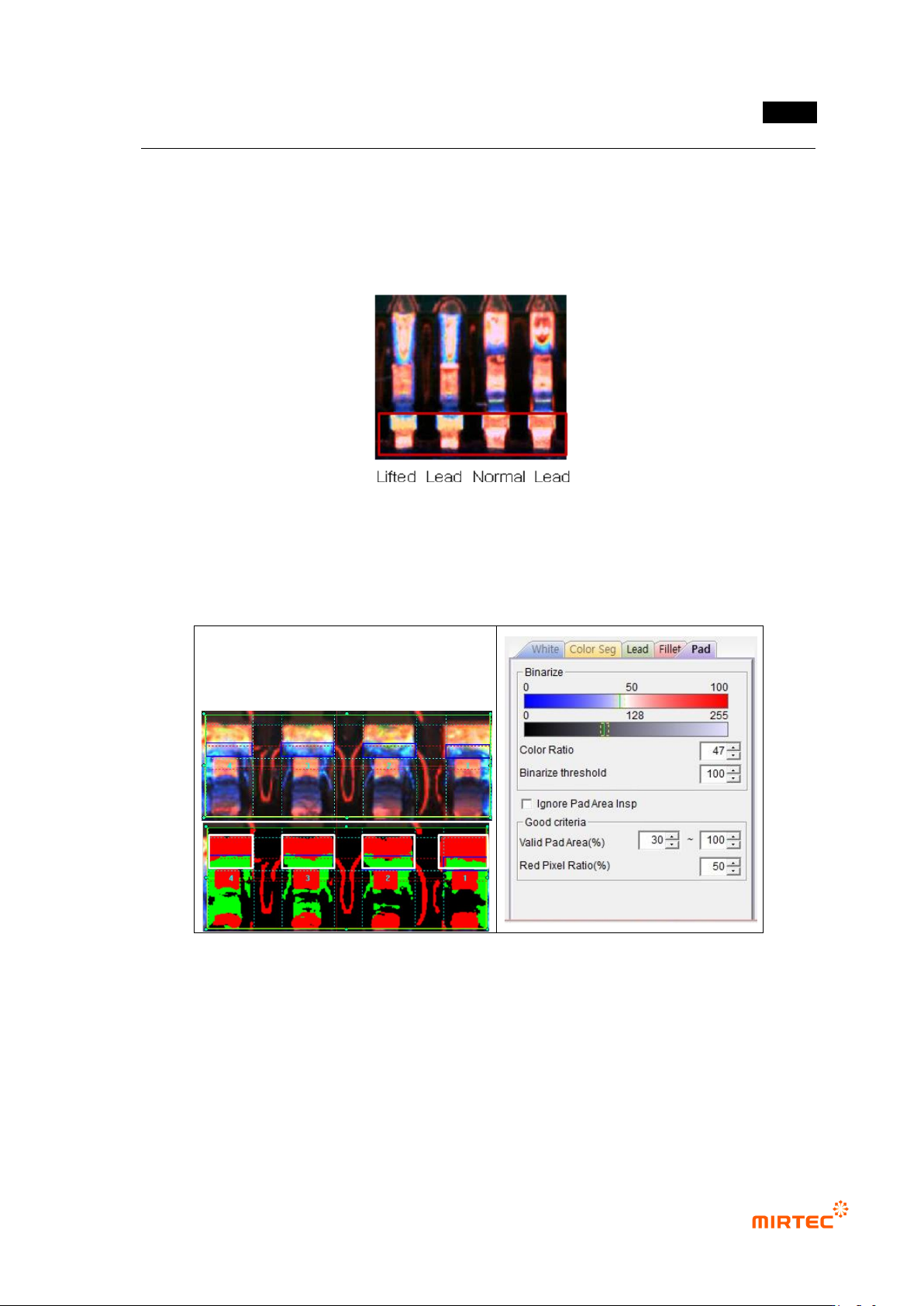
Pad parameter
[Figure 5-151 solder amount inspection setting_pad and preview image]
- Binarization
Use color ratio and binarization boundary value for binarization.
Color ratio: set ratio of red to blue in fillet area. Pixel of which color ratio is above
reference value will be displayed in red, and pixel of which color ratio is below reference
value will be displayed in green.
MV-9 User Manual
5-134
Binarization boundary value: pixel of which red and blue value is below binarization
value will be all „0‟ (black).
- Ignore pad area inspection
Set whether to inspection for pad area or not
- Normal criteria
Effective pad area (%): define ratio of pad area for all of fillet area and pad area and
detect insufficient solder/no solder. Conduct the 2
nd
inspection only when pad area is
between min value and max value. If it is below min value, judge as good. If it is above
max value, judge as insufficient solder/no solder.
Red pixel ratio (%): the 2
nd
inspection for pad area. set ratio of red pixel to total pad area.
If lifted occurs, detect lifted defect using the characteristic of which red area of pad area
narrows. If it is below reference value, judge as defect.
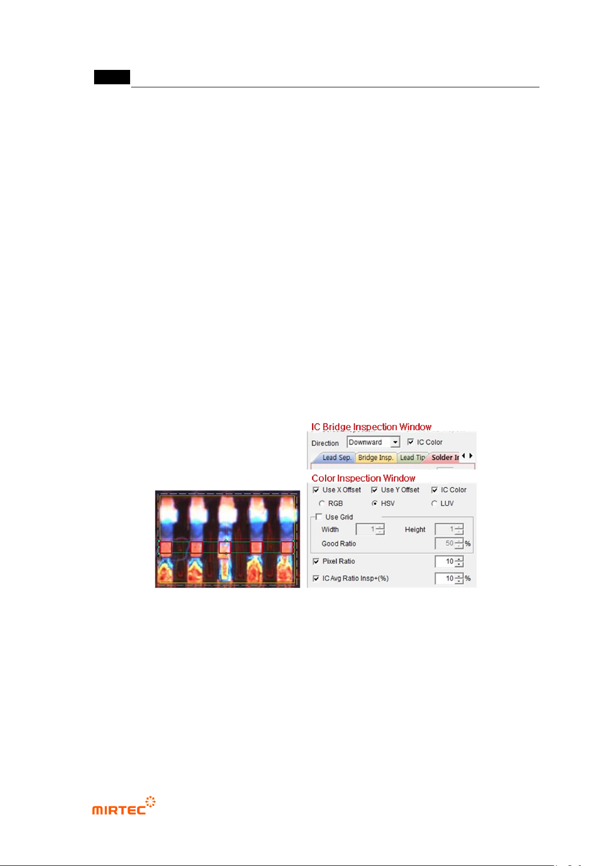
15) Parameter of IC color inspection
- If lifted lead occurs, IC color inspection detects defect using the characteristic of which
lead color is different.
Inspection area is intersection area of lead separation area and color inspection area.
[Figure 5-152 IC color inspection area]
IC Bridge inspection window
- IC color: Select function to inspect lead color by interlocking with color inspection window.
Color inspection window
- IC color: select function for lead color by interlocking with IC Bridge inspection window.
- Pixel ratio: set normal min ratio value to judge good/defect.
- IC average ratio inspection+ (%)
Select for comparison inspection with average value of pixel ratio of all inspection
area
错误!使用“开始”选项卡将 제목 2 应用于要在此处显示的文字。错误!使用“开始”选项卡将 제목 2 应用
于要在此处显示的文字。 .
5-135
Select both of IC color and pixel ratios to activate this.
Min value of normal range is average value – pixel ratio, and max value is average
value + IC average ratio inspection+ (%). (For example, when average value = 50,
pixel ratio=10, IC average ratio inspection+ (%) = 20, normal range min value = 50
– 10 = 45, and normal range max value = 50 + 20 = 70.)
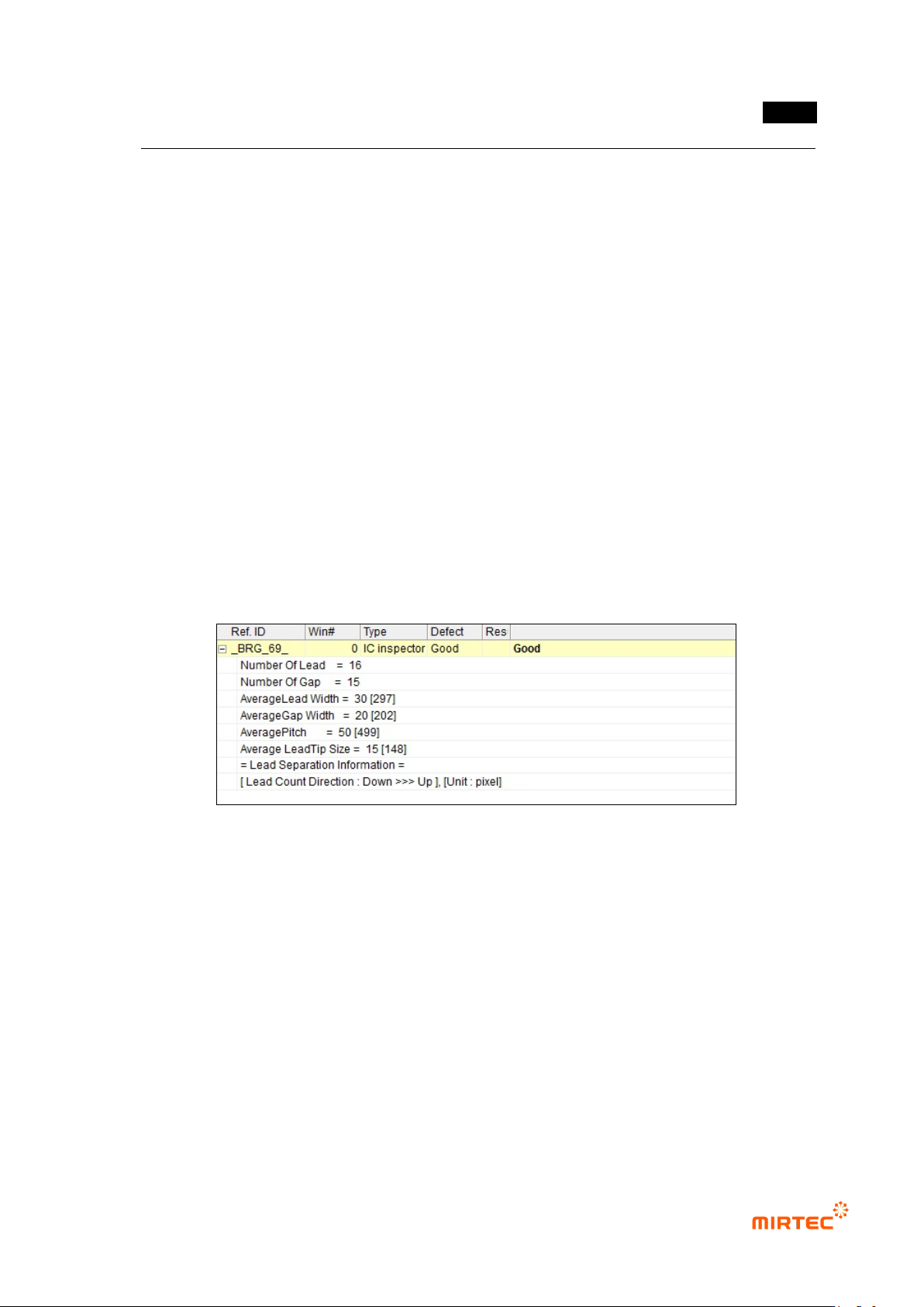
16) Inspection result in status screen
Inspection result (common)
- Number Of Lead: number of lead
- Number Of Gap: the number between lead and lead
- Average Lead Width: average width of lead
- Average Gap Width: average width between lead and lead
- Average Pitch: average distance between lead center
- Average Lead Tip Size: average of lead tip width (value display during solder amount
inspection)
- Lead Count Direction: direction to allot No of each lead
[Figure 5-153 inspection result detail (common)]
IC Bridge inspection result
- Lead Width: width of lead
- Gap: width between lead and lead
- Pitch: distance between lead center