MV-9_Chapter 5. Teaching.pdf - 第11页
错误 ! 使用“开始” 选项卡将 제목 2 应用于要在此处显示的文字。 错误 ! 使用“开始”选项卡将 제목 2 应用 于要在此处显示的 文字。 . 5- 11 ② T o create a new PCB model i n a new folder , as shown in [Figure5- 13 ] , click <folder > button and enter folder name to be newly…
MV-9 User Manual
5-10
[Figure 5-11 conveyor skip mode]
5.2. Creating and opening PCB model
In chapter 5.2, we describe about creating a new PCB model or opening model for which
teaching is already completed.
5.2.1. Creating new model
If there is no model for which teaching is already completed or to create a new model, create a
new model according to the following sequence.
1) Creating a new PCB model
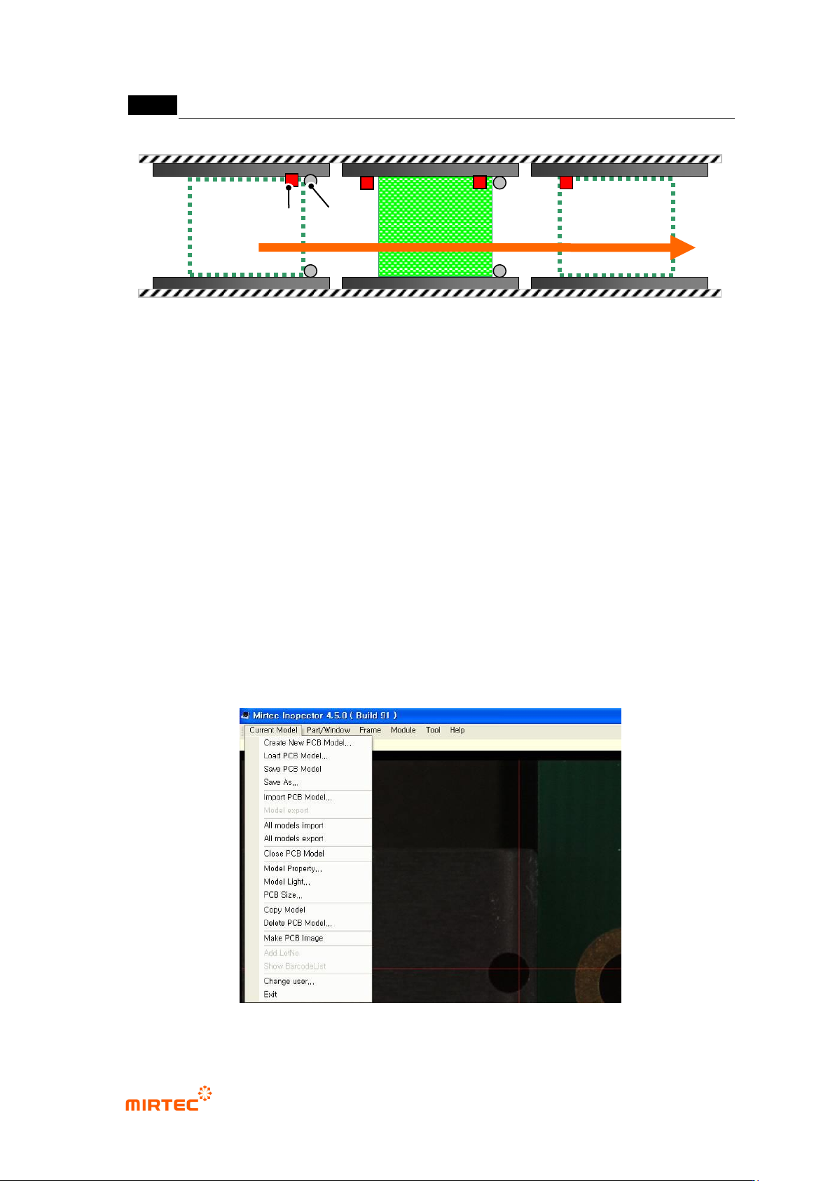
① Select „Create new PCB model‟ in „current model‟.
[Figure 5-12 Screen to create a new PCB model]
[Inlet part]
[Inspection
part]
[Ejection
part]
Sensor Stopper
错误!使用“开始”选项卡将 제목 2 应用于要在此处显示的文字。错误!使用“开始”选项卡将 제목 2 应用
于要在此处显示的文字。 .
5-11
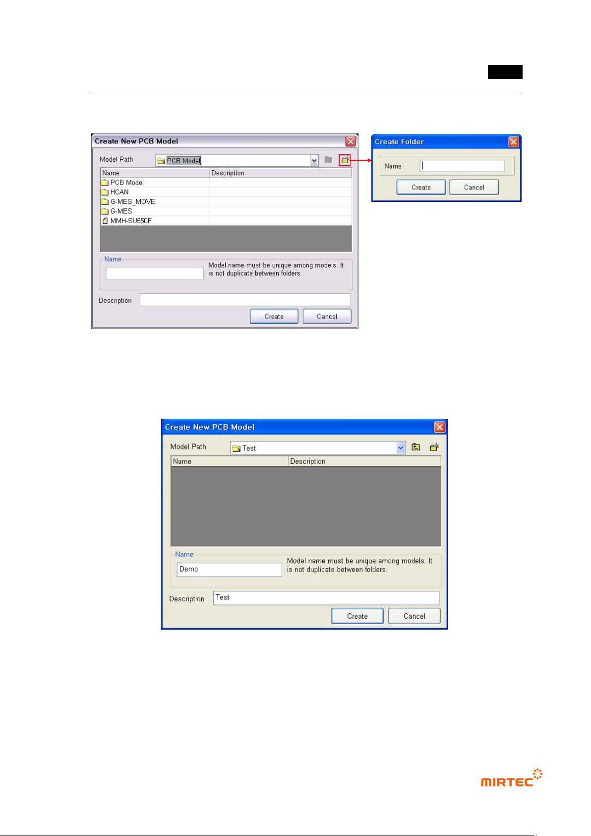
② To create a new PCB model in a new folder, as shown in [Figure5-13], click <folder> button
and enter folder name to be newly created.
[Figure 5-13 screen to create a new PCB model folder]
③ Click newly created folder, input name and description of a model that will be created, and
then click <Create> button. At this point, name of the model to be created must have unique
name among the whole registered model names.
[Figure 5-14 Screen to input name of a new PCB model folder]
④ Register a name of a new PCB model to display model area screen to set PCB area as
shown in the figure below.
MV-9 User Manual
5-12
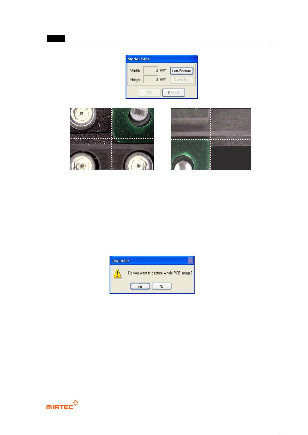
[Figure 5-15 PCB area setting screen]
⑤ Move the robot to the left down part of PCB, click <Down/left> button, and move the robot to
right up part and then click <Up/right> button in model area screen to set the size of new
PCB model. After setting, click <OK> button.
⑥ After size setting of a new PCB model, screen to ask if a user wants to image an image that
will be displayed in whole image screen. Click <Yes (Y)> button to image whole PCB image.
[Figure 5-16 Whole imaging confirmation screen]
⑦ As shown in [Figure5-16], robot will image the whole PCB image from down/left part to
up/right part of PCB. At this point, currently imaged image will be displayed in whole image
screen.
(Left Bottom)
PCB
PCB
(Right Top)