MV-9_Chapter 5. Teaching.pdf - 第269页
错误 ! 使用“开始” 选项卡将 제목 2 应用于要在此处显示的文字。 错误 ! 使用“开始”选项卡将 제목 2 应用 于要在此处显示的 文字。 . 5- 269 position are comp ared for i nspection. * If „Get In fo‟ i s clicked, 3D Model i s displayed. Confirm thro ugh the model if the m easure m…
MV-9 User Manual
5-268
- By using the check box, it is possible to set the height and width together or separately
34 Detailed Setting
- Set the detailed position for the measurement region of the reference surface or height.
- It is possible to store the position with a mouse by using „Click Pos‟ button.
35 Example )
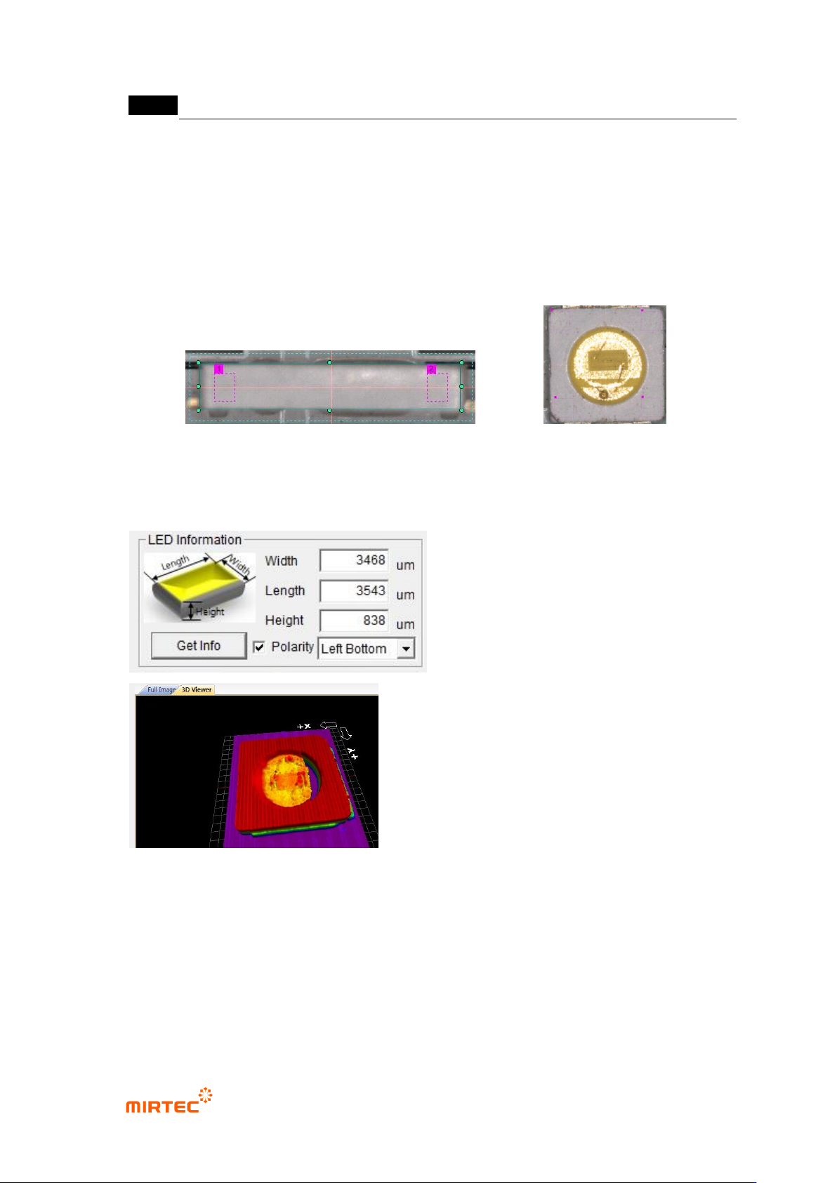
5.9.6 LED PKG. Information Measurement
- If „Get Info (Measurement)‟ is clicked, information on the width, length and height of LED
Pkg. is measured.
- In case of Top View Type, the Polarity position is displayed.
- Though the height is not measured accurately in the area of light release (Epoxy Region),
it does not affect the inspection results since the region is an indifferent region in 3D
inspection.
- By designating the polarity position, the real polarity position and the measured polity
< Top View Type>
<Side View Type>
错误!使用“开始”选项卡将 제목 2 应用于要在此处显示的文字。错误!使用“开始”选项卡将 제목 2 应用
于要在此处显示的文字。 .
5-269
position are compared for inspection.
* If „Get Info‟ is clicked, 3D Model is displayed. Confirm through the model if the
measurement is accomplished normally. (In case the measurement is not normal, it is not
possible to recognize the form of 3D Model.).
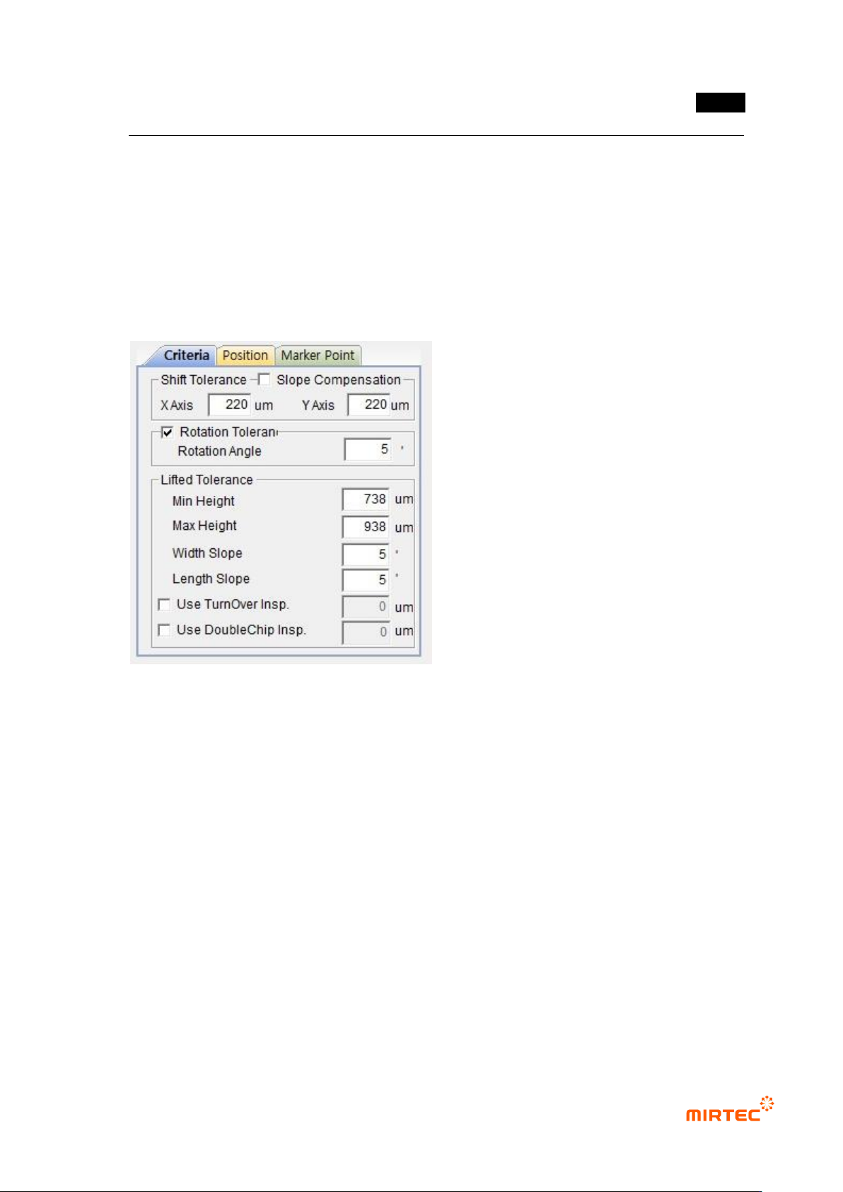
5.9.7 Criteria Setting
36 Shift Tolerance
- X Axis: Set the poor-quality criteria for X-axis shift.
- Y Axis: Set the poor-quality criteria for Y-axis shift.
37 Rotational Tolerance
- Rotational Angle: Set the poor-quality criteria for rotational angles.
38 Lifted Tolerance
- Min Height: Set the poor-quality criteria of the minimum height to inspect LED Pkg.
cracking mishap.
- Max Height: Set the poor-quality criteria of the maximum height to inspect the lifted
quality.
- Width Slope: Set the poor-quality criteria for the lifted angle in the short-axis direction.
- Length Slope: Set the poor-quality criteria for the lifted angle in the long-axis direction.
MV-9 User Manual
5-270
39 TurnOver Insp.: Inspect the turnover.
40 DoubleChip Insp.: Inspect the double chip.
41 Slope Compensation
- Conduct the angle compensation for the slope against the floor surface.
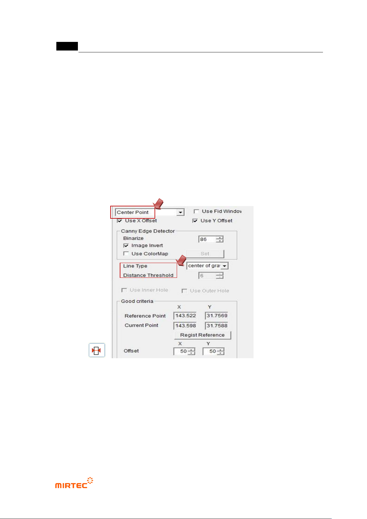
5.9.8 How to Use Markers
In case markers are available around LED PKG., set the center for LED PKG. reference using the
markers.
42 Use the previous inspection window.
- Add the window to the marker part by selecting the previous inspection window
( )..
- Select the Center Point Inspection for the inspection type.
- Set the Line Type in accordance with the form of markers.
- Since the objective is to set the Center Point for LED PKG reference, set large values
for Offset X and Offset Y so that they may not cause poor quality. .
43 Tie the mounting inspection window for 3D BLU and the previous inspection window for
markers into one part.