MV-9_Chapter 5. Teaching.pdf - 第69页
错误 ! 使用“开始” 选项卡将 제목 2 应用于要在此处显示的文字。 错误 ! 使用“开始”选项卡将 제목 2 应用 于要在此处显示的 文字。 . 5- 69 - Refer to „ reference name (page5- 21 )‟ in „5.3.1 m o unting insp ect i on window ‟ exceptin g shape. - Created in „ _BIN_0‟ form at. „BI…
MV-9 User Manual
5-68
5.3.5 Binary inspection window
- Binary inspection can conducts various inspections like line width, edge position, solder
ball, scratch and component center in binary image (image expressed by black and white)
or black and white image (image consisted of pixels with 255steps (black 0 ~ gray 128 ~
white 255) of luminance).
- The followings are detailed inspection types of binary inspection.
Stripe width inspection
position move inspection
solder ball inspection
Tap inspection
multiple tap inspection
eccentricity inspection
Component center
search
comparison inspection
1) Teaching method – commons
① Click <binary inspection window> button among operating buttons.
② Draw binary inspection window in inspection area.
③ Select inspection type.
④ Select X coordinate compensation and Y coordinate compensate. If necessary, select one or
select none.
⑤ Select whether to judge defect as normal
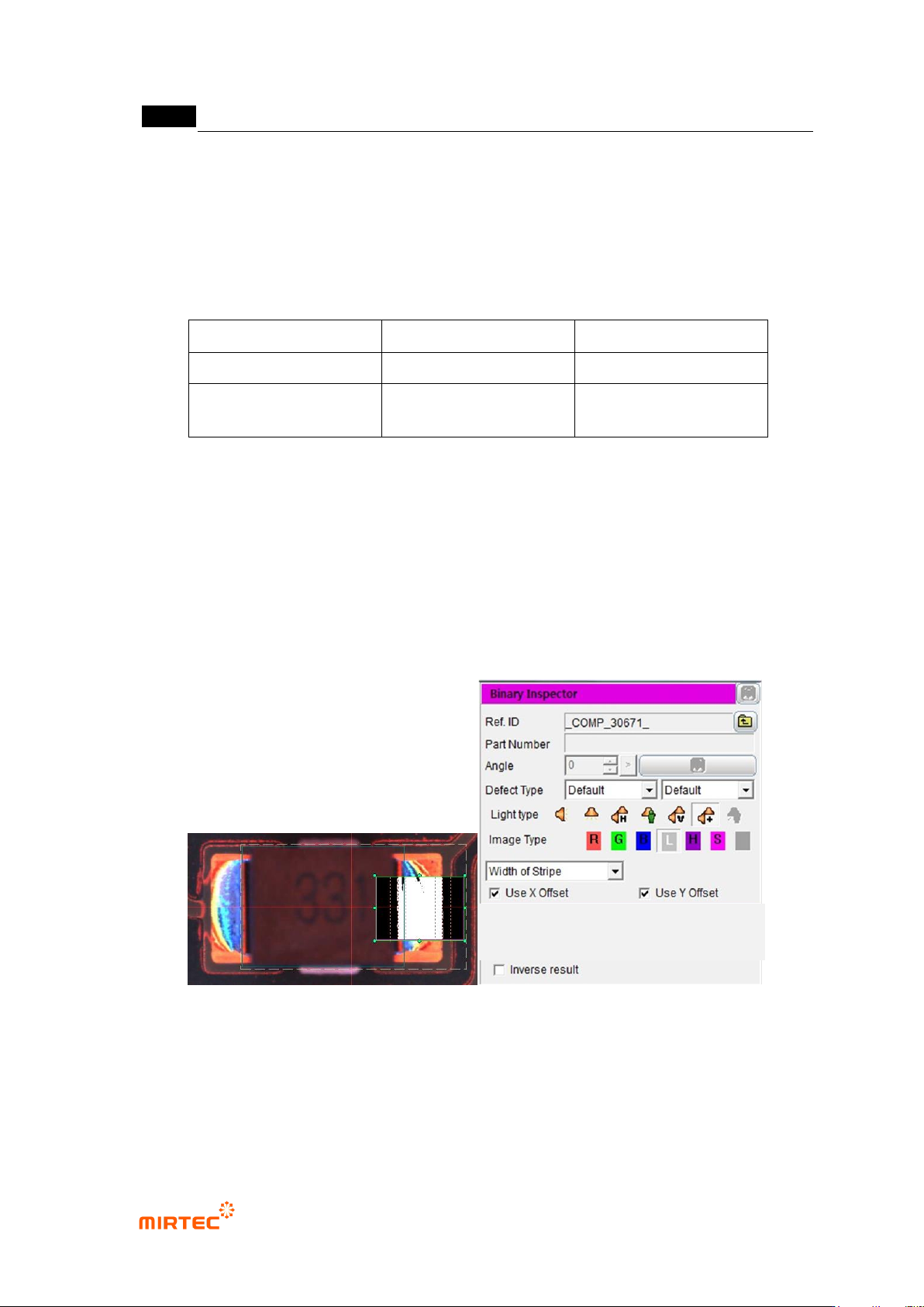
[Figure 5-75 Binary inspection window creation and common parameter]
2) Common parameter
Reference name
错误!使用“开始”选项卡将 제목 2 应用于要在此处显示的文字。错误!使用“开始”选项卡将 제목 2 应用
于要在此处显示的文字。 .
5-69
- Refer to „reference name (page5-21)‟ in „5.3.1mounting inspection window‟ excepting
shape.
- Created in „_BIN_0‟ format. „BIN‟ means Binary and the number means the creation order
of binary inspection window.
Component name
- Refer to „component name (page5-21)‟ in '5.3.1 1mounting inspection window‟.
Rotation angle
- Refer to „rotation angle (page5-22)‟ in '5.3.1 1mounting inspection window‟.
Defect type
- Refer to „defect type (page5-22)‟ in '5.3.1 1mounting inspection window‟.
Light type
- Set light for inspection of inspection window that completed teaching. Select light type that
clearly displays characteristic according to inspection type and inspection area.
Image type
- Set light for inspection of inspection window that completed teaching. Select image type
that clearly displays characteristic according to inspection type and inspection area.
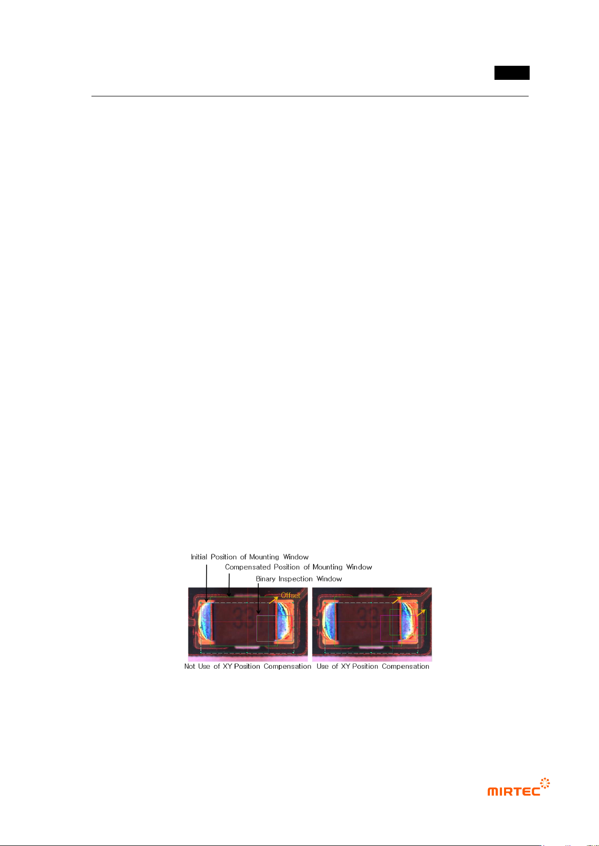
X coordinate compensation, Y coordinate compensation
- If many inspection windows are group to inspect one component, position of other
inspection window can be compensated referring to X/Y offset measured in mounting
inspection window.
- X/Y coordinate compensation is to select whether to conduct position compensation
referring to X/Y offset measured in mounting inspection window.
- As shown in [Figure 5-93], if X/Y coordinate compensation is not used, binary inspection
window doe not move in offset of mounting inspection window. However, in case of using
X/Y coordinate compensation, binary inspection window moves as much as offset.
[Figure 5-76 Use example of X/Y coordinate compensation function]
Judge as good for defect
- Change inspection result judged as defect to normal.
MV-9 User Manual
5-70
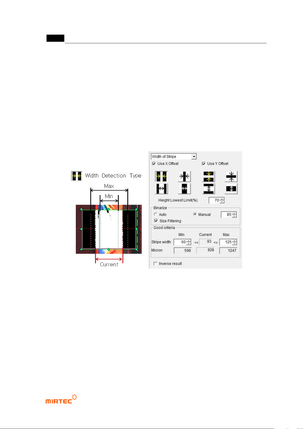
3) Stripe width inspection
- This algorithm is to measure area width and to inspect component shift.
① Teaching method
(a) Draw binary inspection window in inspection area and select stripe width for inspection
type.
(b) Select detection type.
(c) Enter lowest height limit.
(d) Set binarization method and binarization value checking preview image
(e) Enter normal criteria.
[Figure 5-77 Teaching example of stripe width inspection window]