MV-9_Chapter 5. Teaching.pdf - 第167页
错误 ! 使用“开始” 选项卡将 제목 2 应用于要在此处显示的文字。 错误 ! 使用“开始”选项卡将 제목 2 应用 于要在此处显示的 文字。 . 5- 167 5.3.12 IC of fset inspection window - IC offset inspection is algor i thm to i nspect st atus (lead of fse t , l ead sh i ft , le ad tip o…
MV-9 User Manual
5-166
⑦ Group mounting window and resistance color band window into „Group component‟.
⑧ If there are components with same resistance on many parts of substrate, add it in the library,
too.
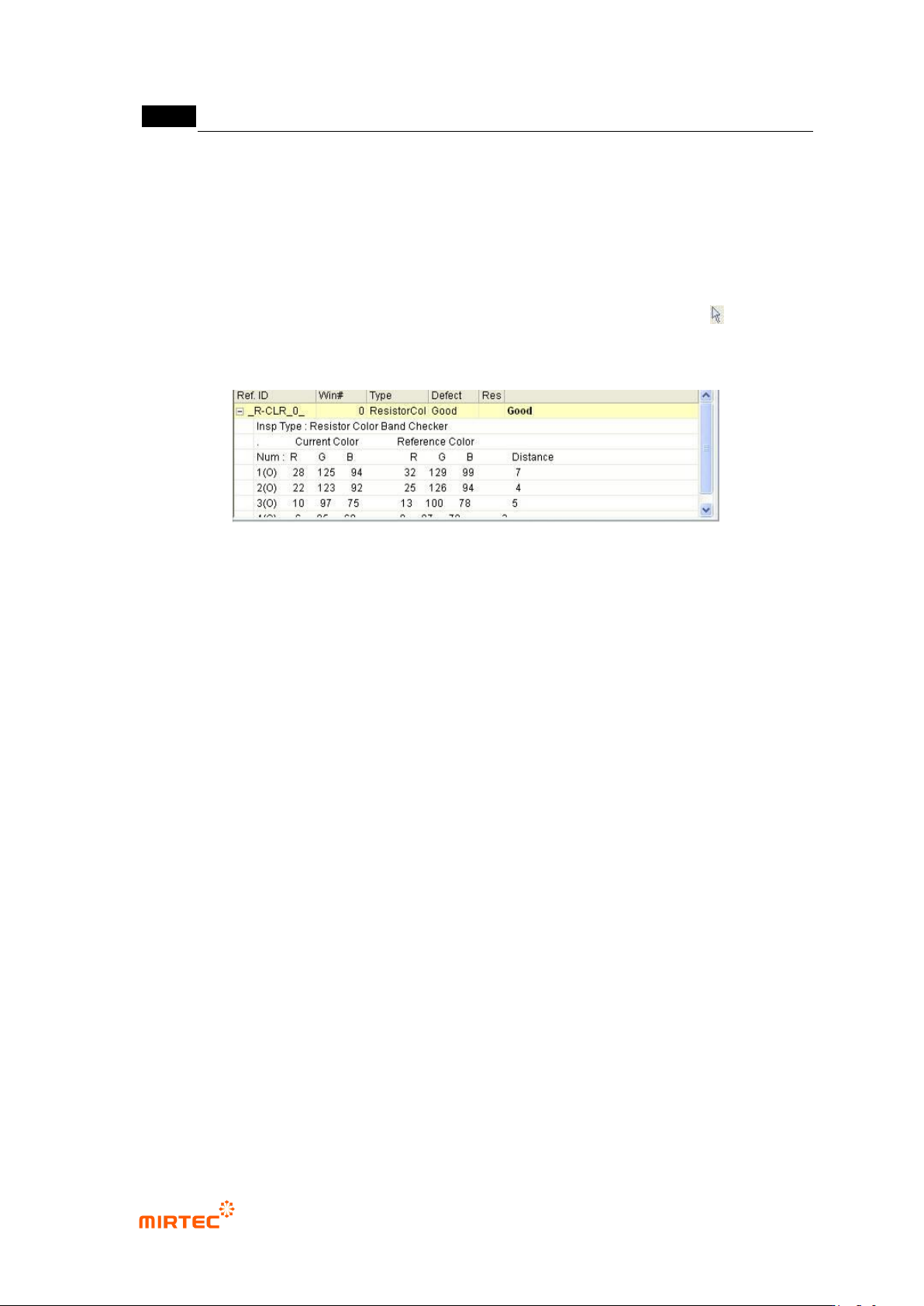
3) Inspection result in status window
For direct inspection of inspection window that completed teaching, select both of mounting
window and resistancecolor band window at the same time using selection button ( ) and select
„inspect‟ in popup menu displyed by clicking right button of the mouse to displaythe following
inspection result in status window in the main screen.
[Figure 5-201 inspection result screen]
Inspection type
This is to display current inspection type.
Current color
Display color of resistance color band inspection window that is currently inspected by color
band order in RGB value.
Reference color
This means inspection reference color. In other words, display resistance color band color of
golden board by RGB value for each detected color band order.
Color distance
This means relative distance of reference color and current color. In case of occurrence of
false defect, adjust min distance in color input window or add reference color to adjust it.

错误!使用“开始”选项卡将 제목 2 应用于要在此处显示的文字。错误!使用“开始”选项卡将 제목 2 应用
于要在此处显示的文字。 .
5-167
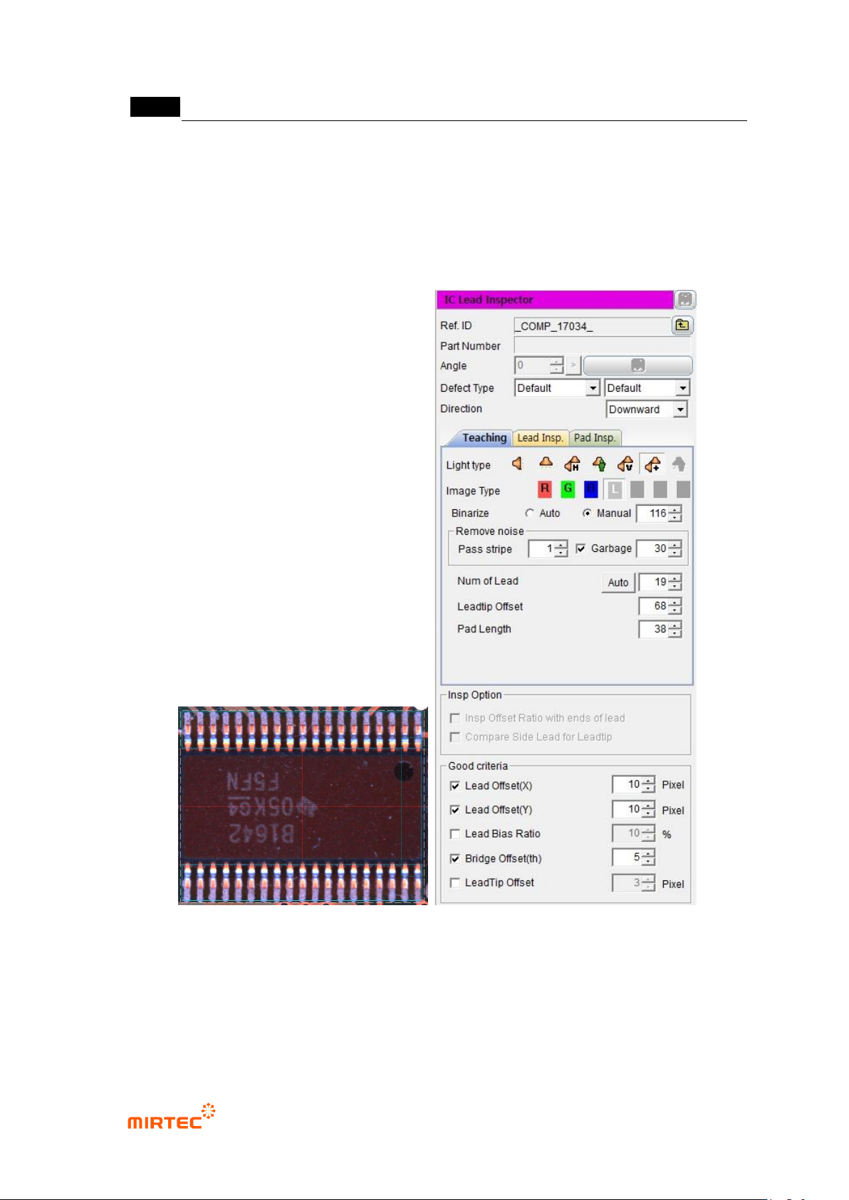
5.3.12 IC offset inspection window
- IC offset inspection is algorithm to inspect status (lead offset, lead shift, lead tip offset) of
IC lead and mounting status (Shift, Tilt) of IC after mounting.
- Besides default light, sub light can be used for lead inspection and pad inspection, and
false defect that can occur under default light can be reduced.
1) Teaching method
① Click <IC offset inspection window> button among operating buttons, and draw window at IC
position of IC desired to be inspected. In general, draw window that is larger than pad area
desired to be inspected.
② Teaching tap teaching
- Select preview in operation window.
- Set light type and image type and binarization for good separation of lead.
- Adjust stripe width and area for noise removal.
- Set number of lead, lead tip, offset, and pad length.
③ Lead inspection tap setting
- Select default light tap, and select light type and inspection type (image type) for lead
inspection.
- Select auto or manual for binarization method. If „manual is set, set binarization value to
clearly display lead.
- Set stripe width and area for noise removal.
- Set search start position, search range, and contrast level for lead inspection. If „auto‟ is
set, check search range auto extraction.
④ Pad inspection teaching
- Select default light tap, and select light type and inspection type (image type) for pad
inspection.
- Select auto or manual for binarization method. If „manual is set, set binarization value to
clearly display pad.
- Set stripe width and area for noise removal.
- Set search start position, search range, and contrast level for pad inspection.
⑤ Check whether to use sub light or not. Select sub light tap that is activated in lead inspection
and pad inspection to set parameter. (light type and image type change)
⑥ Select monitoring option.
MV-9 User Manual
5-168
⑦ Set reference value for inspection items and good/defect judgment for each item in normal
criteria
2) Teaching example of representative component
[Figure 5-202 Teaching example of mounting inspection window]
3) Inspection parameter
Reference name
- Refer to „reference name‟ in „5.3.1 mounting inspection window‟ excepting shape.