MV-9_Chapter 5. Teaching.pdf - 第120页
MV -9 Use r Manual 5- 120 „ m e asured pitch < m ax pitch tha t com ple ted te achi ng ‟ condition is inspection for lead loss or short between lead. - Width of each measured lead < average pitch : inspect short …

错误!使用“开始”选项卡将 제목 2 应用于要在此处显示的文字。错误!使用“开始”选项卡将 제목 2 应用
于要在此处显示的文字。 .
5-119
- Average lead pitch
Parameter that is automatically set by clicking reset during teaching. Average pitch
value between each lead calculated after lead separation. When average lead
pitch value is refreshed, max/min lead pitch value will be also automatically
refreshed.
- Min lead pitch
value calculated based on average lead pitch or entered by user. If interval
between lead separated during inspection is below this value, inspection window
will be judged as defect. When average lead pitch value is refreshed, this value
will be automatically calculate and set again by the following formula.
Min lead pitch = average lead pitch ⅹ 0.6
- Max lead pitch
value calculated based on average lead pitch or entered by user. If interval
between lead separated during inspection is above this value, inspection window
will be judged as defect.
Max lead pitch = average lead pitch ⅹ 1.3
- Use average pitch width during inspection
conduct Bridge inspection based on calculated average lead pitch value not using
lead separation during inspection.
- Lead gap/width inspection
When this is set, value is automatically set. However, random value can be set. If
lead width is larger than setting value or gap width is smaller, judge as defect. (Ex:
detect lead bending or lead shift.)
Lead separation verification
- Basically, lead separation is to get gap area that is inspection area for Bridge inspection.
However, if inspection is conducted when wrong parameter is set, there is no lead at which
should be lead or lead is recognized where there is no lead by noise. In this case, lead
separation does not properly conduct, there will be problem to correctly recognize bridge
error. Hence, to prevent this, use max/min lead pitch parameter to verify proper lead
separation after lead separation.
- Check lead separation and lead information using max/min pitch whether lead pitch is
smaller than min lead pitch or whether there is larger lead than max lead pitch to make
defect occurs to increase reliability of lead separation.
Normal judgment criteria in Bridge inspection window
- Min pitch that completed teaching < measured pitch < max pitch that completed teaching
inspection of foreign material between lead for condition of „min pitch that
completed teaching < measured pitch‟
MV-9 User Manual
5-120
„measured pitch < max pitch that completed teaching‟ condition is inspection for
lead loss or short between lead.
- Width of each measured lead < average pitch: inspect short status of 2 lead
- Should be no connection between each lead: inspect short status of 2 lead
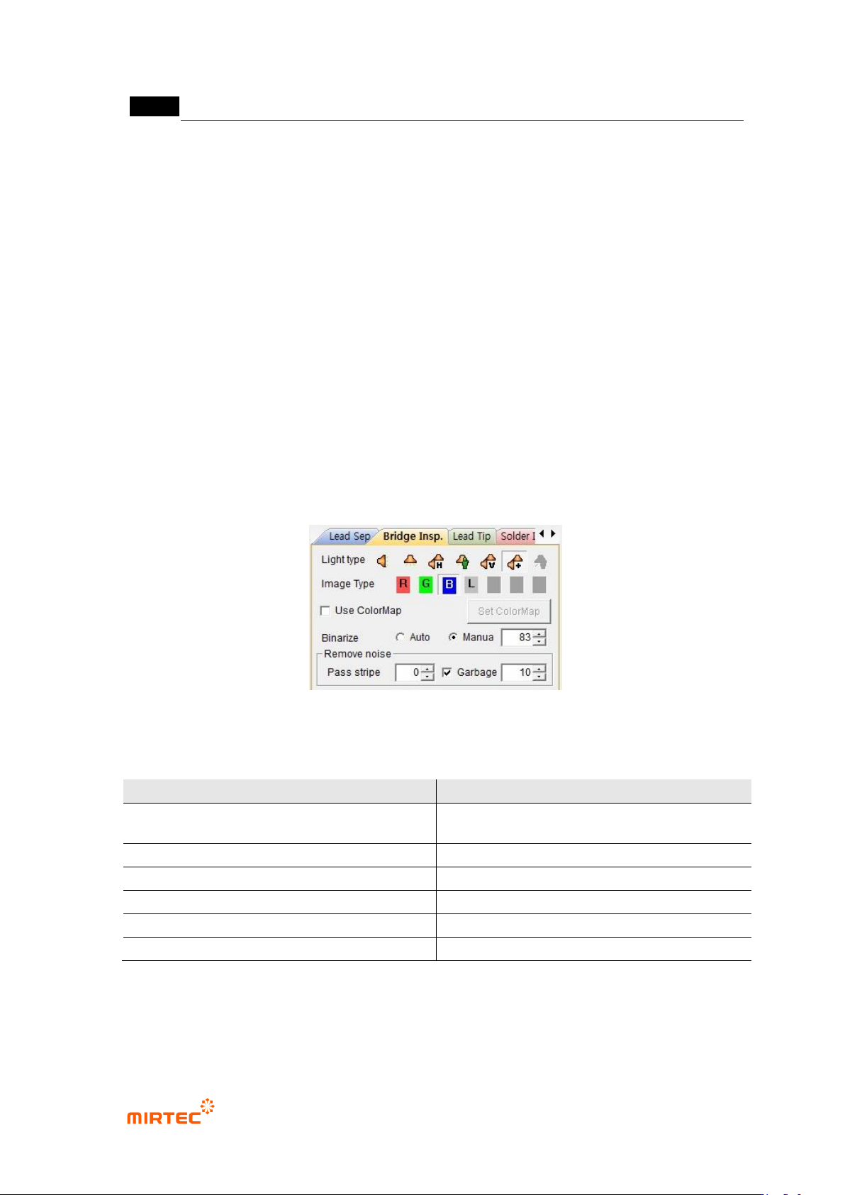
11) Bridge inspection parameter
- For bridge inspection parameter, adjust image status to display all parts suspected as
defect in preview image.
- In general, use low binarization value and stripe width of about „0‟. all lights can check
solder wire part in binarization status. However, select horizontal + vertical light and select
B as image type, and solder wire check is easy through image.
- In case of much noise on IC lead according to Flux or PCB status, too low stripe or small
area removal is cause to increase false defect during inspection. Hence, in case of some
substrates, stripe or small area removal needed to be smoothly used.
[Figure 5-132 Bridge inspection parameter]
[Table 5-10 Bridge inspection setting value]
Item
Recommended setting value
light
horizontal + vertical light (Sometimes
horizontal)
image type
B (L for horizontal light)
binarization type
manual
binarization level
Low value (50 ~ 150)
stripe
Low value (0 ~ 1)
area
Low value (0 ~ 20)
错误!使用“开始”选项卡将 제목 2 应用于要在此处显示的文字。错误!使用“开始”选项卡将 제목 2 应用
于要在此处显示的文字。 .
5-121
[Figure 5-133 Bridge defect example]
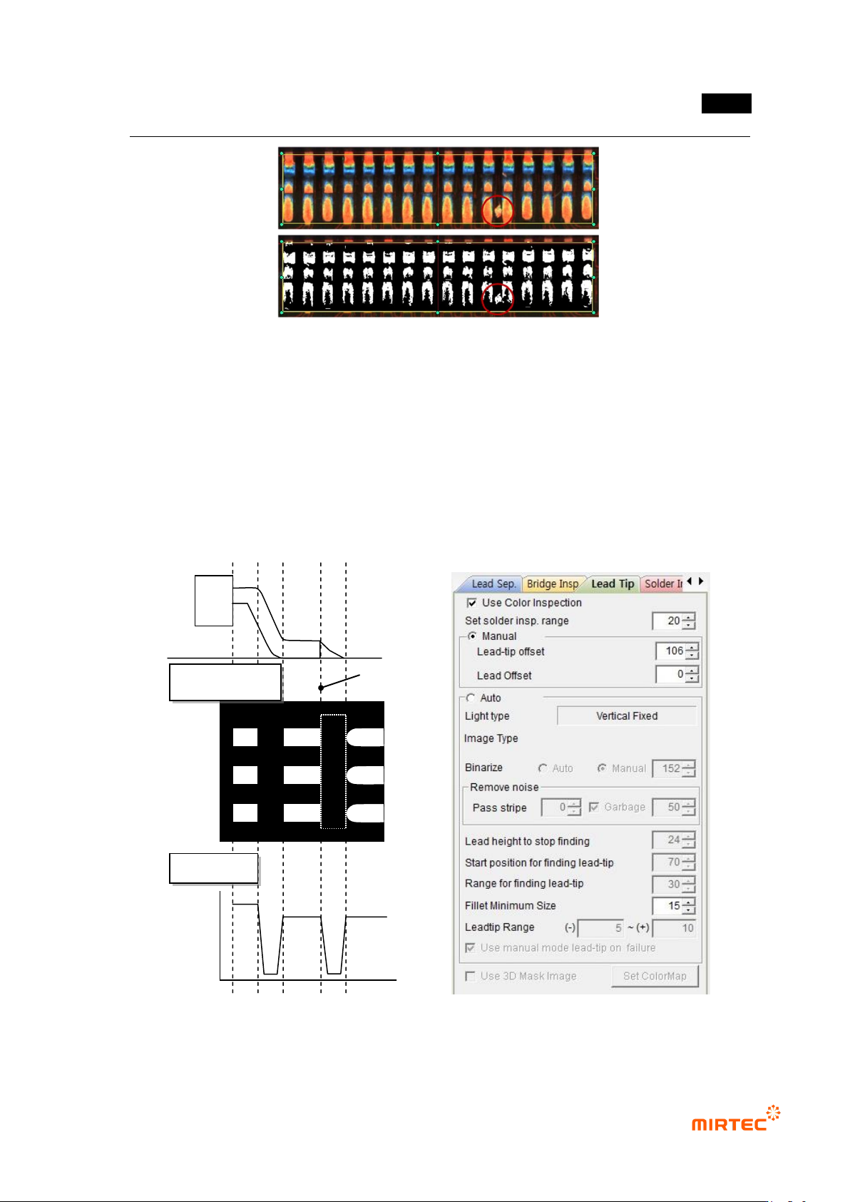
12) Lead tip parameter
- Check at solder amount inspection among default parameters to activate lead tip tap and
solder amount inspection tap.
- For lead tip position, set start point of fillet area for solder amount inspection. For setting
method of lead tip, there are manual setting to set lead tip position by user and auto
setting method at which program finds lead tip position.
[Figure 5-134 lead image characteristic and lead tip parameter]
Lead tip position
Binarization image
Profile