MV-9_Chapter 5. Teaching.pdf - 第161页
错误 ! 使用“开始” 选项卡将 제목 2 应用于要在此处显示的文字。 错误 ! 使用“开始”选项卡将 제목 2 应用 于要在此处显示的 文字。 . 5- 161 com ponen t through tr i angulation m ethod . In case of com pone nt with high height, it interrupt s laser re f l ection. Hence, so l ve …
MV-9 User Manual
5-160
This option is to compensate angle of rotation structure of laser sensor.
Top: 0 degree, left: 90 degree, bottom: 180 degree, right: 270 degree
Scan speed
Scan speed can be set to „1 ~ 5‟, and has same function with low speed 1, low speed 2,
middle speed, high speed 1, high speed 2 set in „laser calibration‟ in „Config.‟.
Average value
Set to detect lifted defect of package by scanning upper package side.
Max/min
Set this item to detect lifted defect by scanning lead tip. In general, set min value to −5000 not
to give influence on inspection. In case of much noise during measurement, increase window
size and remove noise by using middle value filter.
Min height and max height
Click „measure‟ to collect data and set it to proper value.
Effective range auto setting
Value set in „laser auto range setting ratio‟ will be applied in „teaching‟ setting screen of „4.2.1
operation setting‟ in „Chapter 4 Config.‟ to automatically set min/max height.
Teaching method
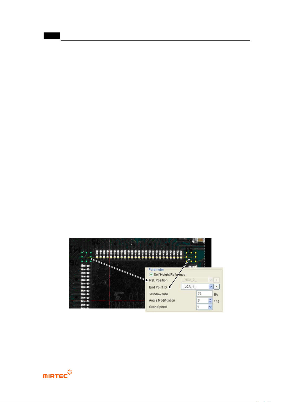
① Click <lifted inspection window> button among „operating buttons‟. Drag from beginning to
end of IC Bridge desired for teaching to create 2 lifted inspection windows at start point and
end point, and automatically set end window ID.
[Figure 5-193. lifted inspection window reference position and end position setting]
② Position setting: set each of „reference position window‟ and „end window‟.
③ Start position (reference position): set „angle compensate‟ of „lifted inspection window‟. laser
that is used for the machine measures height using the laser reflected from the measuring
错误!使用“开始”选项卡将 제목 2 应用于要在此处显示的文字。错误!使用“开始”选项卡将 제목 2 应用
于要在此处显示的文字。 .
5-161
component through triangulation method. In case of component with high height, it interrupts
laser reflection. Hence, solve the problem using angle compensation of laser device.
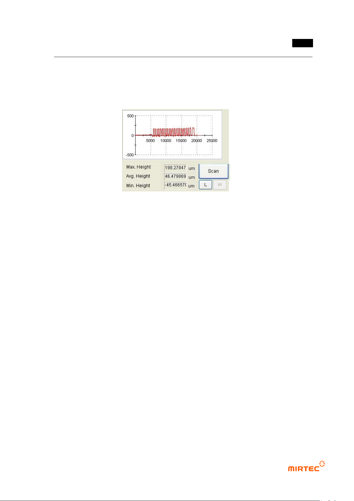
④ Click <Measure> button to get height of part desired to be measured comparing to reference
height.
[Figure 5-194 lifted inspection window reference height measurement]
⑤ Set min height and max height that will be used for measurement. If solder window of IC
Bridge exceeds min/max value, it will be detected das defect during measurement.
5.3.11 Resistance color band inspection window
Resistance color band inspection window is to inspect wrong mounting of component by
inspecting the color of color band of axial type resistance (Resistor) mounted on PCB.
1) Parameter of resistance color band inspection window
MV-9 User Manual
5-162
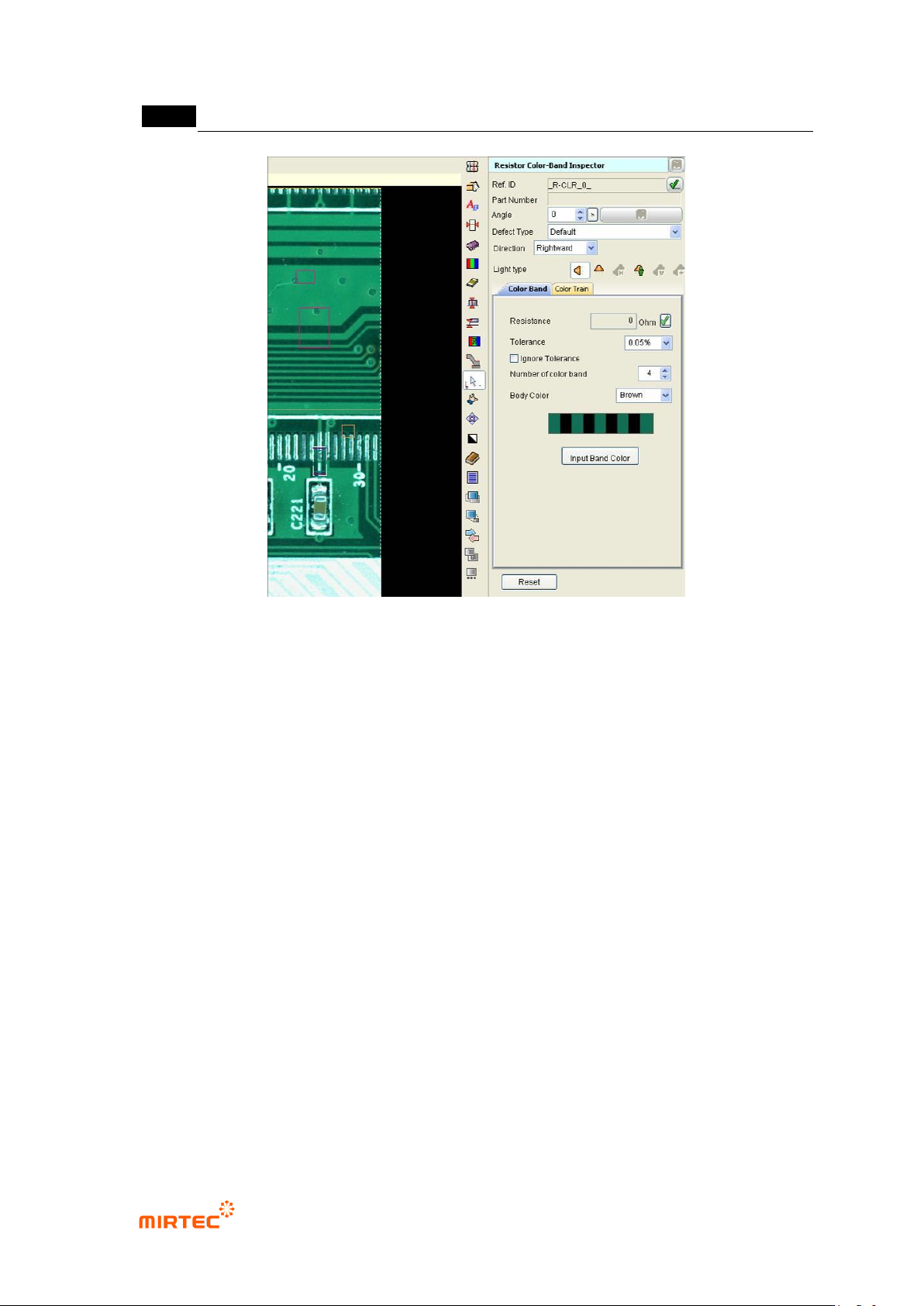
[Figure 5-195 Screen to create resistance color band inspection window] Direction
Reference name
Refer to „reference name‟ in „5.3.1 mounting inspection window‟ excepting shape.
Name is created in „_R∙CLR_1_‟ format. „R∙CLR‟ mean Resistor color and the number means
creation order of color inspection window.
Component name
Give name to one resistance component. Since 2 inspection windows of resistance color band
are created, group inspection windows into one component. If necessary, enter component
name. For more information, refer to „component name‟ in „5.3.1 mounting inspection window‟
Rotation angle
Display angle of inspection window in 0 ~ 359° unit.
Angle of window created by manual teaching will be always displayed by 0°, and inspection
window rotates counterclockwise based on the current position. If inspection window is created
by using ATT, angle information of the relevant component will be displayed.
Rotate component to properly change direction of color band resistance according to rotation
angle.
Defect type
Refer to „defect type‟ in '5.3.1 mounting inspection window‟
.