MV-9_Chapter 5. Teaching.pdf - 第192页
MV -9 Use r Manual 5- 192 [Figure 5- 236 whole images of side cameras] 5.3.15 T eaching by using divided light This function is used t o inspe ct s older defe ct or Polari ty , lifted and others of com ponen t . T each…
错误!使用“开始”选项卡将 제목 2 应用于要在此处显示的文字。错误!使用“开始”选项卡将 제목 2 应用
于要在此处显示的文字。 .
5-191
5.3.14 Teaching by using side viewer
Use this option to inspect component of which component height is high and solder area is not
clear.
Teaching method
① Click desired inspection window button among general-purpose/exclusive inspection
windows.
② Change camera using camera selection button and conduct teaching using same method for
main camera.
[Figure 5-234 camera selection button (main, north/south/east/west, total]
main camera image
image from south direction camera
[Figure 5-235 Teaching example using side viewer]
As shown in [Figure5-147], even teaching for solder area that is not clearly displayed by main
camera can be easily done if side cameras are used and more correct inspection can be
conducted.
Since the frame of side cameras are fixed frames, if camera is different even for teaching at the
same position, „Group component‟ can‟t be done.
③ If component that completed teaching is selected in the frame, click <All> button after
activating of <All> button among camera selection buttons to display images imaged by all
cameras as shown in [Figure5-148].
MV-9 User Manual
5-192
[Figure 5-236 whole images of side cameras]
5.3.15 Teaching by using divided light
This function is used to inspect solder defect or Polarity, lifted and others of component.
Teaching method
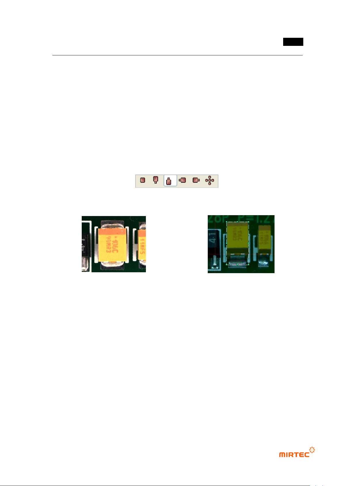
① Click desired inspection window button among general-purpose/exclusive inspection window.
② Teaching method is same with component teaching method of horizontal light. select
horizontal light and change light to desired light when divided light button is activated before
teaching.
[Figure 5-237 divided light button (All horizontal, north/south/east/west)]
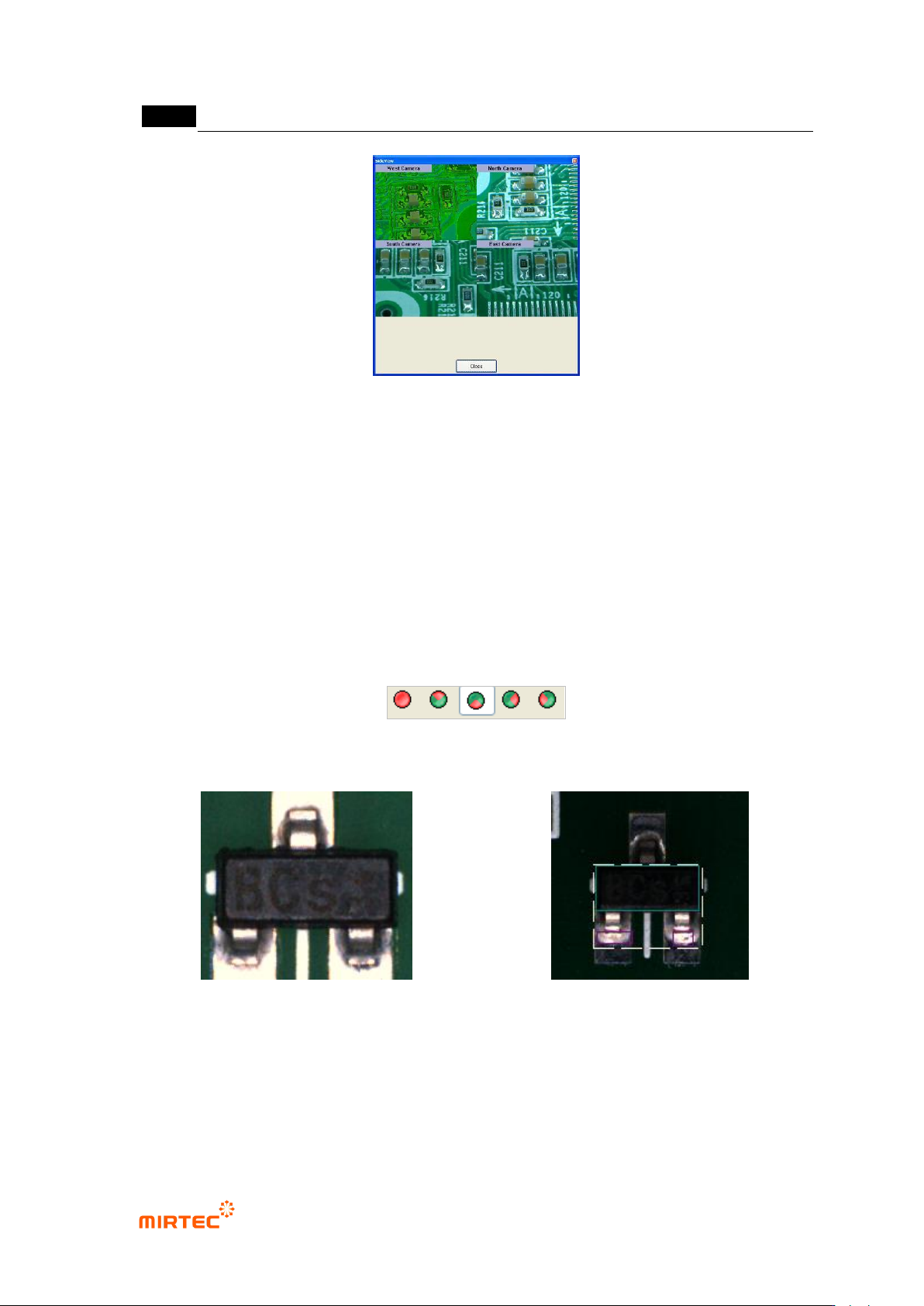
horizontal total light image
divided light image
[Figure 5-238 Teaching example using divided light]
③ [Figure5-150] shows image that is imaged in horizontal total light. That shows teaching of
mounting inspection window in the vertical light and solder teaching and „Group component‟
in the divided light (south). Like this, if divided light is used, more precise inspection for
soldering area or Polarity is possible.
错误!使用“开始”选项卡将 제목 2 应用于要在此处显示的文字。错误!使用“开始”选项卡将 제목 2 应用
于要在此处显示的文字。 .
5-193
5.4 LED BLU inspection
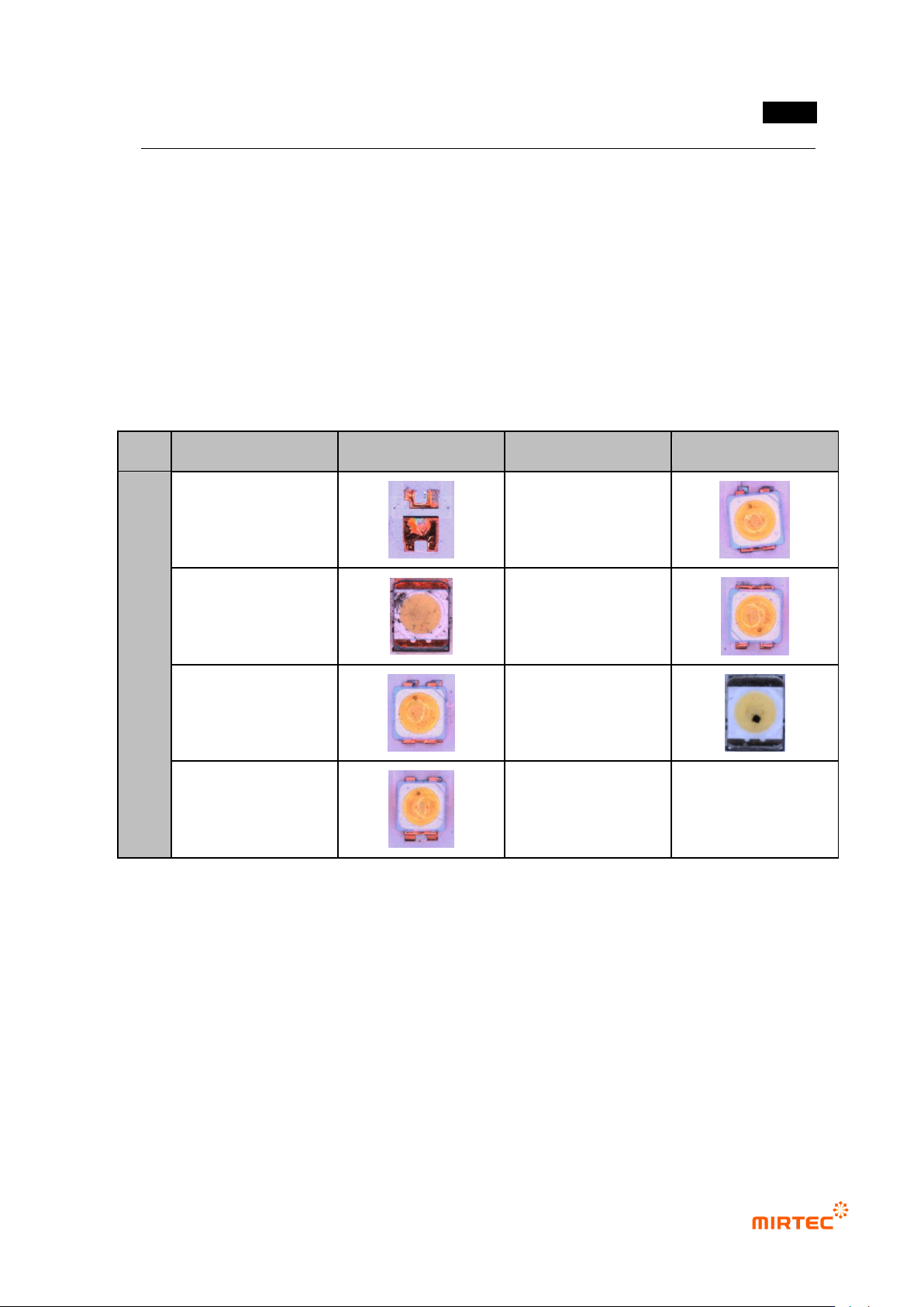
- LED BLU inspection can conduct 3D inspection and 2D inspection. 3D inspection conduct
s lifted, Polarity, shift inspection of LED package using mounting window. 2D inspection
detects LED package defect types using position move inspection and component center
search function of mounting inspection, solder inspection, color inspection and binary
inspection as shown in [Table 5-16].
[Table 5-16 LED package defect type]
Detection item
Top view type
detection item
Top view type
PK
G
Non-mounting
Rotation
Damage
Polarity
X shift
Foreign material
Y shift
1) Config.
① For BLU inspection, check at „Use BLU inspection‟ on the bottom of the setting window in
login-option.
② Display of setting measurement data
- Display measured data as a CSV file or set the save path. Select [tool - Config. – data
export] in Inspector menu, and set the following 2 items.
- Check at „Save measurement data‟ to save the following 2 items.