MV-9_Chapter 5. Teaching.pdf - 第255页
错误 ! 使用“开始” 选项卡将 제목 2 应用于要在此处显示的文字。 错误 ! 使用“开始”选项卡将 제목 2 应用 于要在此处显示的 文字。 . 5- 255 5.7.4 Selection of Mounting T ype Select “ N ormal” in the m ounti ng type. 5.7.5 Position Setting ⑭ Setting of Exp and Si ze - Deci de th…
MV-9 User Manual
5-254
5.7 Odd Parts
The objective is to inspect the lift of odd parts (BGA, Connector, etc.).
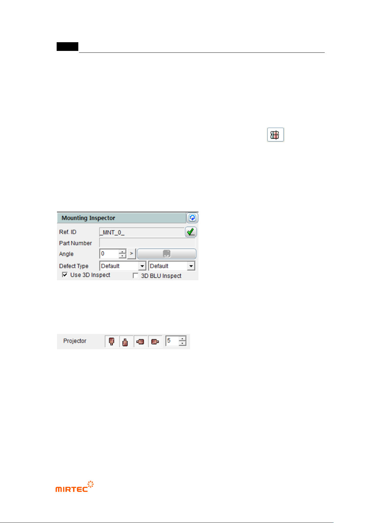
5.7.1 Selection of Window for Mounting Inspection
With the window button, select and add the window for mounting inspection.( ).
* In general, a new window is not added and “Use 3D Inspect“ option is checked and used on
the window for mounting inspection which has already been taught.
5.7.2 Selection of “Use 3D Inspect “ Option
Check “Use 3D Inspect” item in the window parameters for mounting inspection.
5.7.3 Projector Selection
Select the projector to be used in the inspection.
- It is possible to select the east, west, south and north projectors, and they are selected
by default values.
- In general, it is recommended that 4 projectors be used.
In case only one projector is used, the measurement may not be made due to noise.
.
错误!使用“开始”选项卡将 제목 2 应用于要在此处显示的文字。错误!使用“开始”选项卡将 제목 2 应用
于要在此处显示的文字。 .
5-255
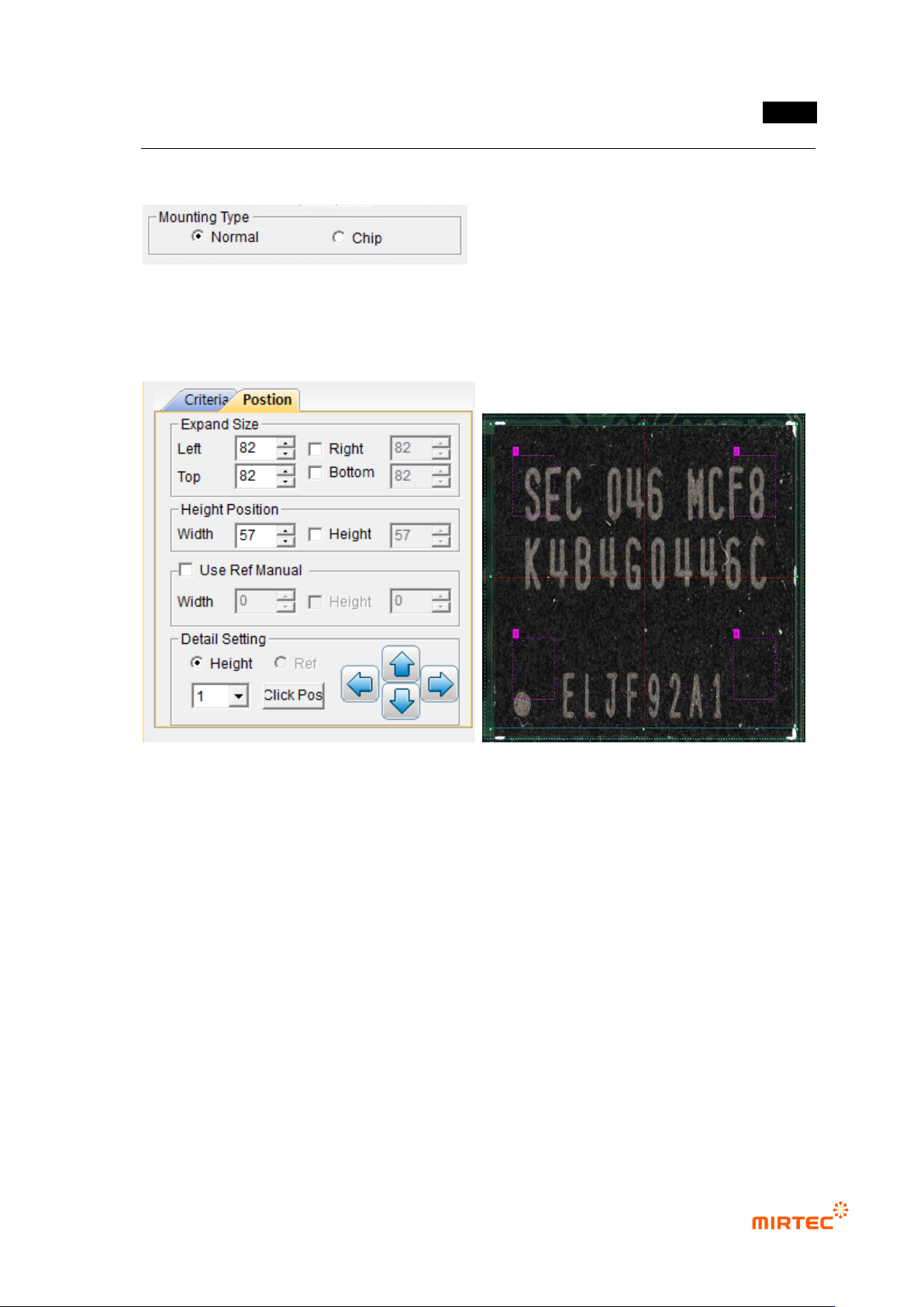
5.7.4 Selection of Mounting Type
Select “Normal” in the mounting type.
5.7.5 Position Setting
⑭ Setting of Expand Size
- Decide the expanded size for planar information with respect to the floor (PCB or
reference).
- Include the floor surface from all the directions of left, right, top and bottom.
- Mark the expanded area with yellow dotted lines.
Setting of Height Position
- Set the position to calculate the average height of the electrode part at both ends.
Mark the height position with red dotted lines.
⑮ Use Ref Manual (Setting of Reference Surface)
- Set manually the region for planar information.
- It is possible to set the height and size together or separately by using the check box.
MV-9 User Manual
5-256
⑯ Detailed Setting
- Set the detailed position for measurement regions of the reference surface and height.
- It is possible to designate the position with a mouse by using „Click Pos‟ button.
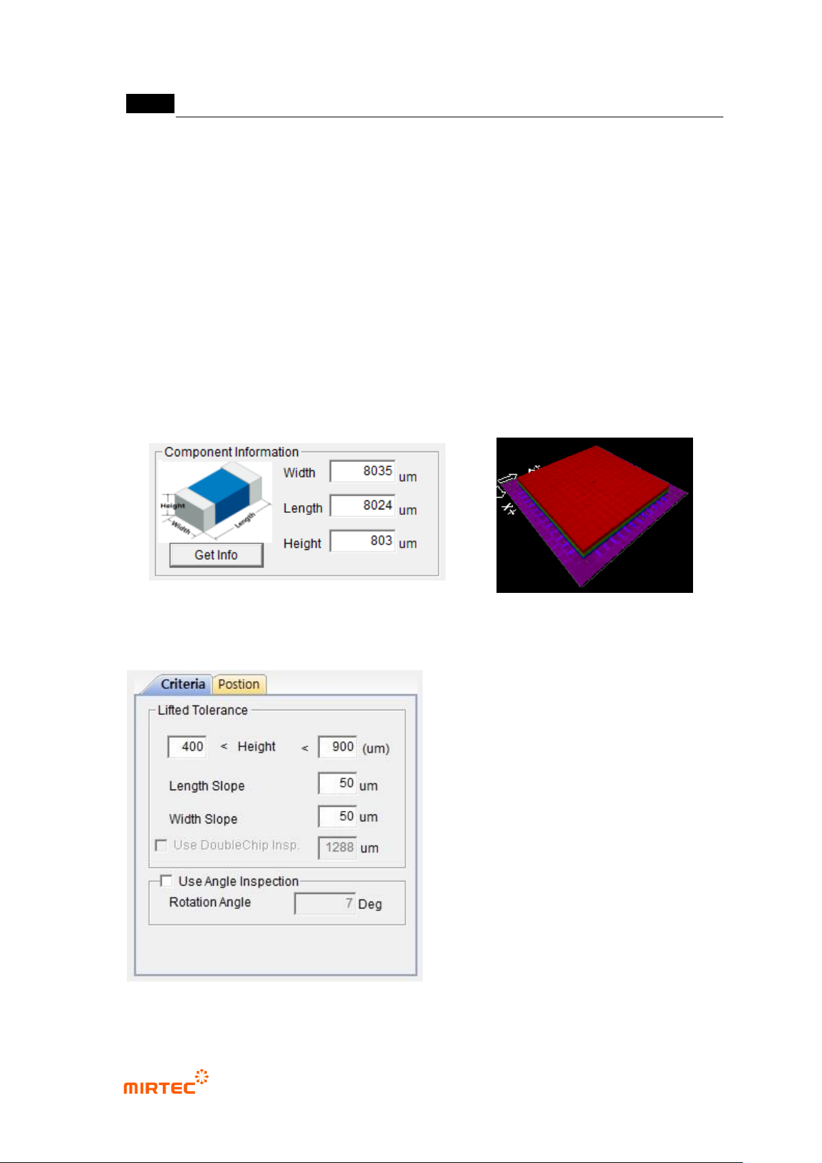
5.7.6 Part information Measurement
Click „Get Info (Measurement)‟ to measure information on the width, depth and height of parts.
* Click „Get Info‟ to display 3D Model, and confirm through the model if the information is normally
measured. (In case it is not measured normally, it is impossible to identify the form of 3D
Model.).
5.7.7 Criteria Setting