MV-9_Chapter 5. Teaching.pdf - 第198页
MV -9 Use r Manual 5- 198 - T o de tect foreign m aterial , only fluorescent subst ance area is inspected. Therefo re , set electrode area as „Don‟t care region‟ . If electrode of LED package appears, regard it as „Don‟t…
错误!使用“开始”选项卡将 제목 2 应用于要在此处显示的文字。错误!使用“开始”选项卡将 제목 2 应用
于要在此处显示的文字。 .
5-197
(Reference: reference point will be created by chemical etching and it will have about
50um of processing error.)
2) Teaching method
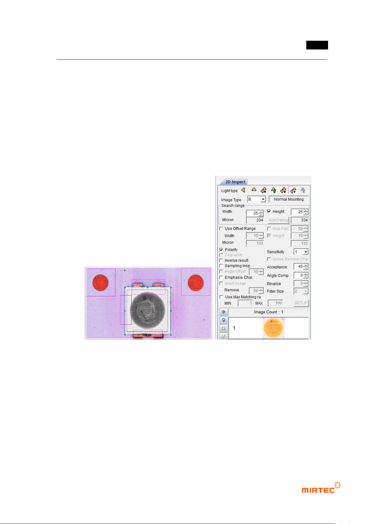
① Teaching and setting mounting inspection
- Conduct non-mounting, damage, and turnover inspection through mounting inspection.
- Select color light, and select image type by changing R, G, B, and L to select the clearest
image type. Since LED has polarity, we check at polarity.
[Figure 5-243 Mounting inspection setting and preview image]
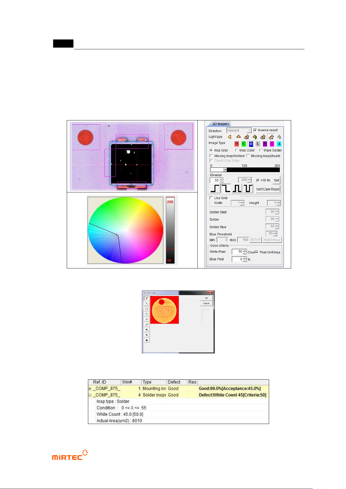
② Foreign material inspection (solder inspection) teaching and setting
- The purpose of foreign material inspection is to inspect foreign material on fluorescent
substance surface. For this purpose, we use solder inspection window.
- Select proper light type and image type to detect foreign material in Fluorescent substance
area of LED package. If foreign material appears in black, adjust color map to detect
foreign material.
- Select general inspection for inspection type.
MV-9 User Manual
5-198
- To detect foreign material, only fluorescent substance area is inspected. Therefore, set
electrode area as „Don‟t care region‟. If electrode of LED package appears, regard it as
„Don‟t care region‟.
- Check at pixel unit inspection, and enter allowable number of max white pixel for normal
criteria
[Figure 5-244 Foreign material inspection setting and preview image]
[Figure 5-245 ‘Don’t care region’ setting]
错误!使用“开始”选项卡将 제목 2 应用于要在此处显示的文字。错误!使用“开始”选项卡将 제목 2 应用
于要在此处显示的文字。 .
5-199
[Figure 5-246 Foreign material inspection result]
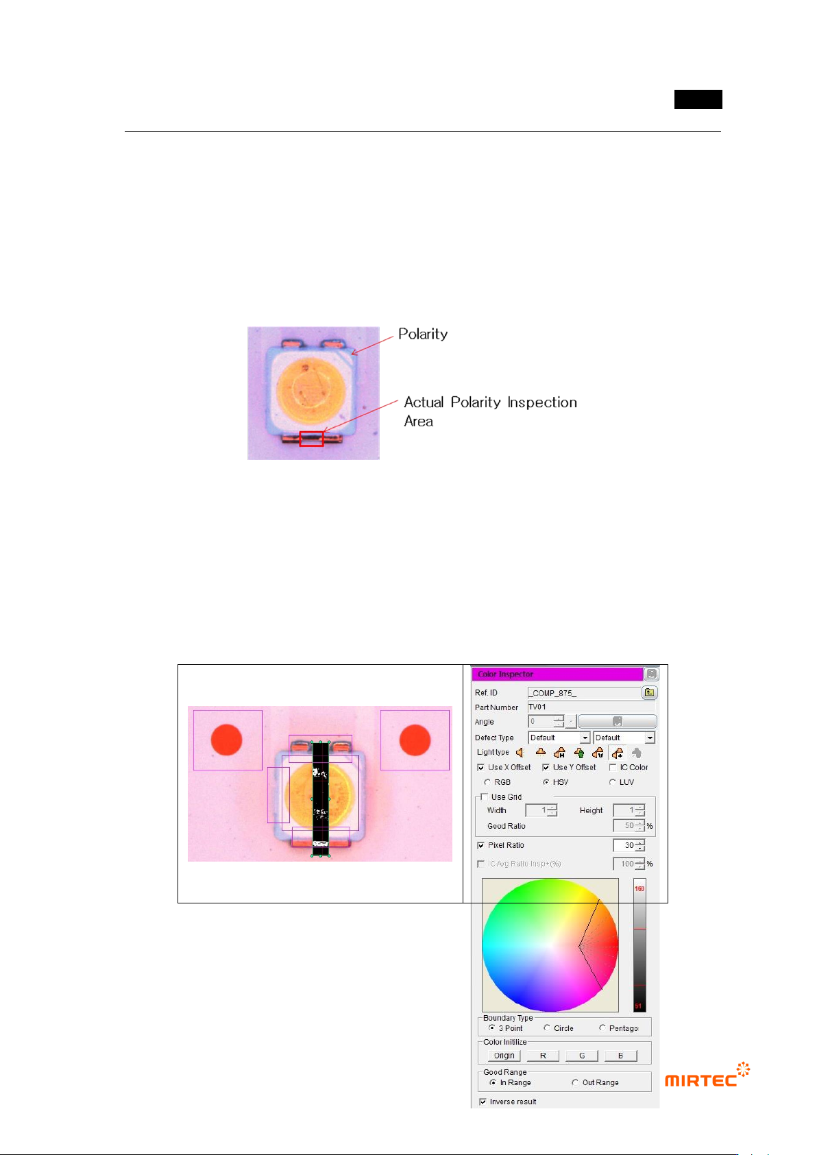
③ Teaching and setting Polarity inspection (color inspection)
- Polarity inspection is to detect mounted polarity of LED package, judge whether polarity
exists or not. In general, TV has a polarity mark (so called chamfering) on one corner of
package. However, since detection status differs from package, detect area difference
between LED electrodes using color inspection algorithm.
[Figure 5-247 Polarity inspection area]
- Conduct Polarity inspection through inspection for area between electrode and electrode
using color inspection window.
- Select HSV for color coordinator, and select pixel ratio.
- Adjust color map for electrode separation. If white pixel appears in area that completed
teaching, it is LED Polarity. Hence, check at “judge defect as normal”.