N7201A616E00_0317.pdf - 第287页
NPM-W 2 EJM7DE-MB-04O-0 0 2 Choose a component name 2 3 + ● The head moves to the selected componen t position. A 4 ● Change each lighting value of coaxial1, coaxial2, middle angle and lower angle then adjust the image w…
NPM-W2 EJM7DE-MB-04O-00
Checking the lighting condition (Unnecessary under normal condition)
The lighting adjustment function is used only if it is difficult to inspect components under normal lighting
conditions.
Move the inspection head to a component location, and, checking the image, adjust the lighting to the
condition (high contrast condition) best suited for inspection. For your information, if applying the adjusted
lighting condition for the inspection condition, set the lighting condition in 2D inspection editor on a per-
component basis.(→[NPM-DGS 2D inspection editor])
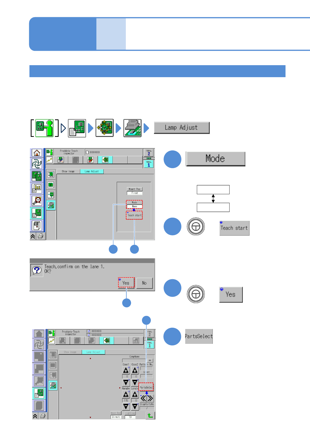
Operating procedure
4-3-2
1
Name
Comment
●Choose the component search
mode.
2
+
1
■When the mode is a component name
1
Produc-
tion data
and
teach
Capturing the images of
teaching PCB
(PCB after component
placed)
3
1 2
3
3
Confirm the message
4-3-2-5
(PCB is loaded, and the component
search/image confirmation screen is
displayed)
●A message appears in the absence of
any PCBs in the upstream machine.)
+
NPM-W2 EJM7DE-MB-04O-00
2
Choose a component name
2
3
+
●The head moves to the selected
component position.
A
4
●Change each lighting value of coaxial1,
coaxial2, middle angle and lower angle
then adjust the image which is suitable
for inspection.
5
+
3
4 5
A
(Returns to the next layer up.)
4-3-2-6
Component
inspection
(Returns to the next layer up.)
(The inspection head moves to another
part of the same component name)
●Use to check an image of another part.
●Check the screen for the imaging
capability suitable for inspection while
changing each lighting value.
●In adopting the adjusted lighting value
to inspection condition, record the
adjusted value
6
6
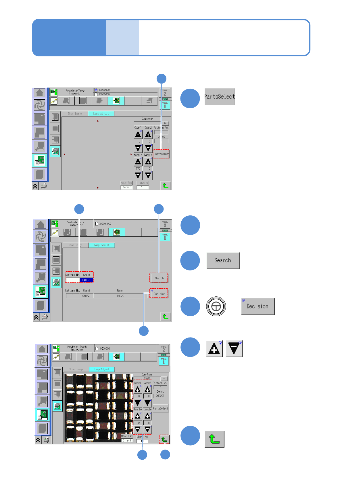
NPM-W2 EJM7DE-MB-04O-00
Operating procedure
4-3-2
1
■When the mode is comment
1
(The screen where you select the
component to check its image condition
is displayed.)
2
3
5
4
Enter the pattern number and
the comment
2
3
(The comment information that matches
the entered data is displayed on the
screen.)
4
+
●The head moves to the selected
component position.
5
Produc-
tion data
and
teach
Capturing the images of
teaching PCB
(PCB after component
placed)
4
(Returns to the next layer up.)
4-3-2-7
●Change each lighting value of coaxial1,
coaxial2, middle angle and lower angle
then adjust the image which is suitable
for inspection.
●Check the screen for the imaging
capability suitable for inspection while
changing each lighting value.
●In adopting the adjusted lighting value to
inspection condition, record the adjusted
value
6
6