N7201A616E00_0317.pdf - 第677页
NPM-W 2 EJM7DE-MB-09O -00 9-1-3 -4 At a glance
NPM-W2 EJM7DE-MB-09O-00
2 570
1 616954
1 095.5
820.5 1 511.5
2 570
1 055.5
571943.5
810
571 951
1 830
1 080
2 000
1190
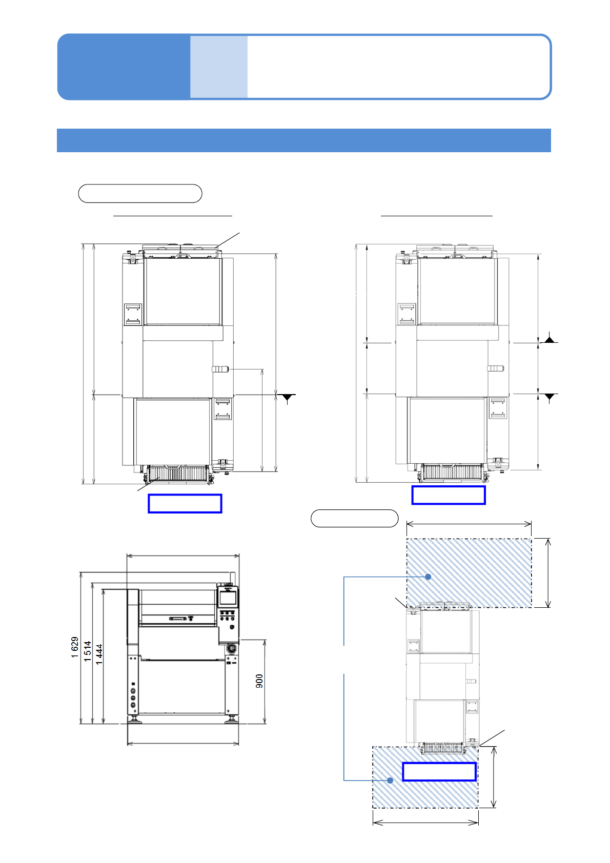
Outside dimensions
and working area 2
9-1-3-3
■When the tray feeder is connected
Twin tray specifications
Working
area
(Unit: mm)
Outside dimensions
Working area
Feeder cart
Twin tray feeder
Cover end
face
Cover end
face
Specifi-
cation
Operating procedure
9-1-3
1 280 (Conveyor width)
1 265 (Cover outline)
Front side
Front side
1 280 (Conveyor width)
1 265 (Cover outline)
Front side
Single conveyor specification Dual conveyor specification
PCB transport
reference
PCB transport
reference
(Rear lane)
PCB transport
reference
(Front lane)
PCB transport height

NPM-W2 EJM7DE-MB-09O-00
9-1-3-4
At
a glance
NPM-W2 EJM7DE-MB-09O-00
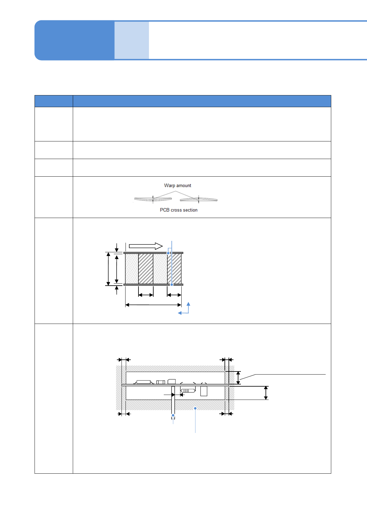
Applicable PCB
specifications 1
Item Single conveyor
Dimensions
(mm)
●Min
L 50 W 50
●Max
L 750 W 550
Thickness
(mm)
0.3 to 8.0 (Dot dispensing: 0.5 to 8.0 )
Mass
(kg)
3 or under (after placement)
Allowable
PCB warp
(mm)
Placement
and
dispensing
area
(mm)
Dead
space
(mm)
9-1-4-1
3
28
16-nozzle head : Max. 6.5
12-nozzle head : Max. 6.5
8-nozzle head : Max. 12
3-nozzle head : Max. 30
Dispensing head : Max. 28
No component area
PCB support pin
No component
area
Y
X Fixed side
Keep 2 mm away from the component on the reverse side.
●If you want to create your own PCB-support blocks, please consult us.
Warp lower: within 0.5
Warp upper: within 0.5
3
3
3
Placement area
a: 50 to 550
b: 44 to 542
c: 3.0
d: 50 to 750
d
1,d2: 50 to 350
*1)
*1)
*1)
Dispence area
a: 50 to 550
b: 42 to 542
c: 4.0
d: 50 to 750
d
1,d2: 50 to 350
*1)
Specifi-
cation
Operating procedure
9-1-4
a b
c
d
c
d2 d1
PCB flow
*1) When two PCBs are clamped