N7201A616E00_0317.pdf - 第345页
NPM-W 2 EJM7DE-MB-05 O-00 G (Displays detailed error information) A B E F C D B A C D E F G 5-4-3 -6 Returns to the previous screen. 2 Shape Other Position The number of displacement inspe ction errors. Fill The nu mber …
NPM-W2 EJM7DE-MB-05O-00
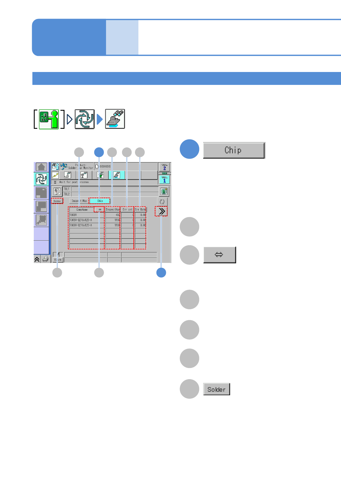
This is used to identify and take measures against the causes of defects in cases where a certain component
produces a high concentration of defects.
Inspection monitor 3
Operating procedure
5-4-3
Produc-
tion
5-4-3-5
Error Cnt
Err Rate
InspectNum
CompName
The number of components judged as
defective in inspection.
(The number of errors/ the number of
inspection ) x 100(%)
A
B
D
E
C
F
Scrolls to display a long component name.
Switches between component inspection
and solder inspection.
1
Component
1
B
C D EA
F
2
NPM-W2 EJM7DE-MB-05O-00
G
(Displays detailed error information)
A
B
E
F
C
D
BA C D E F
G
5-4-3-6
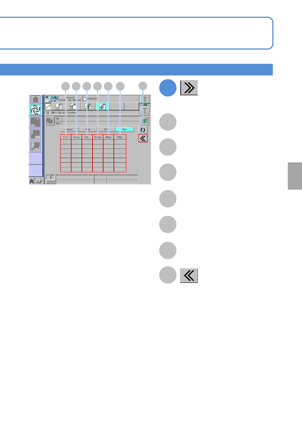
Returns to the previous screen.
2
Shape
Other
Position
The number of displacement inspection
errors.
Fill
The number of shape errors.
The number of other errors.
Perva
Bridging
The number of bridging inspection errors.
The number of blur inspection errors.
The number of oozing inspection errors.
Solder
inspection
NPM-W2 EJM7DE-MB-05O-00
Wrong judgment input
screen 1
Operating procedure
5-4-4
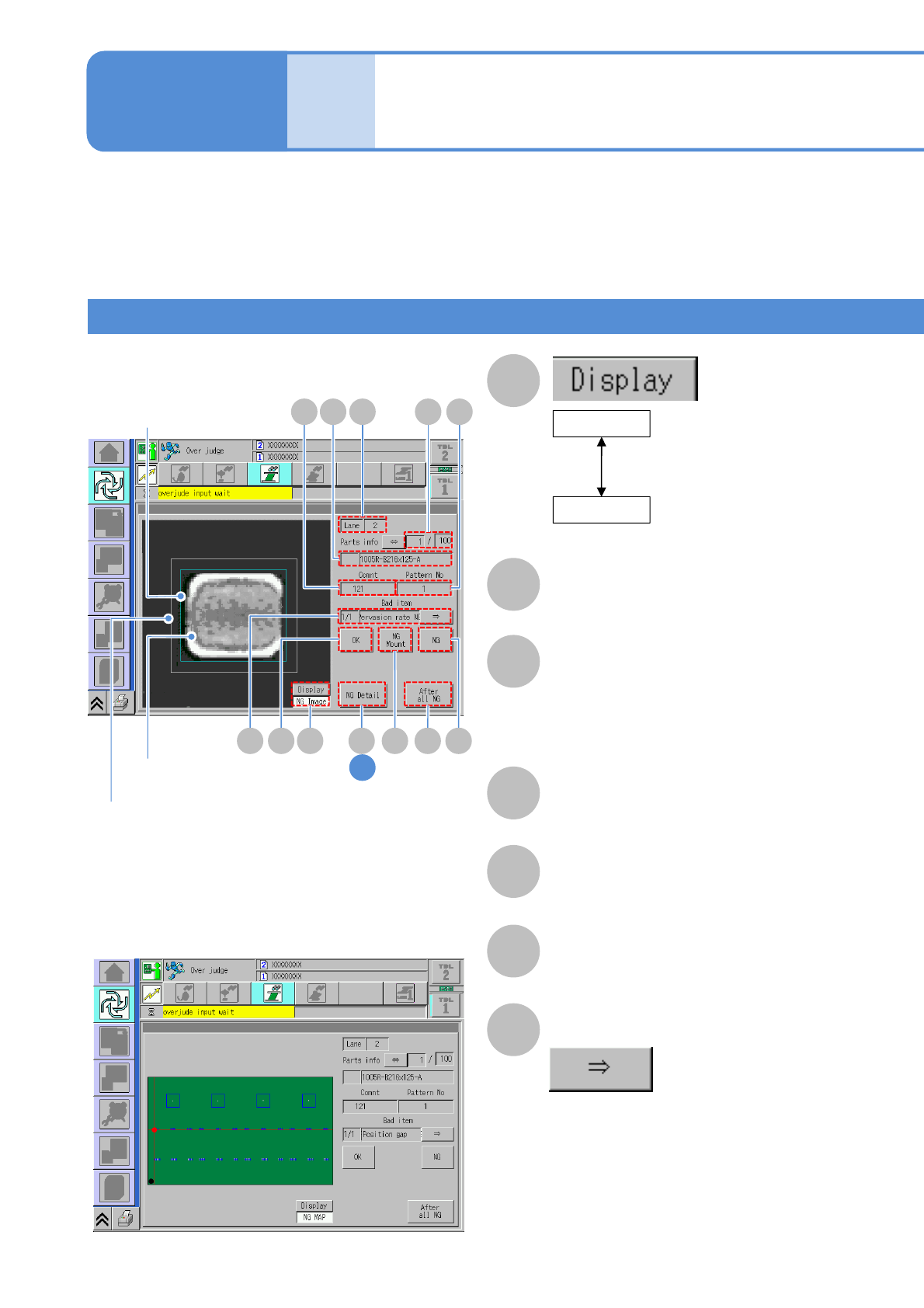
The wrong judgment screen is displayed when an inspection result turns out to be defective.
(The following screen will not be displayed and a defective PCB is unloaded as it is if the soft switch (→P.5-2-
1) for [Over judge check] is OFF.)
●Check visually any inspection-NG location displayed on the screen and set it as either nonconforming or
conforming (misjudgment) before resuming production.
●If you want to set solder inspection condition during placement processing after wrong judgment input,
(→P.5-5-2)
A
B
E
Comment
F
Pattern No
C
Lane
D
Comp info
Name of placement component (part
name).
■NG image display
■NG MAP display
(Component inspection /
solder inspection)
Displays the image that
makes a nonconforming
judgment at the moment
Lane No.
Blue frame in the image:
Solder position misalignment
tolerance
Green frame in the image:
Solder data external frame
White frame in the image:
Solder search area
G
CDE F
H JLA
B
NG image
(Component inspection /
solder inspection)
Displays any NG location
on PCB on the map.
NG MAP
IK
G
Produc-
tion
5-4-4-1
1
Over judgment input
Bad item
Displays other defective items.
Denominator/Numerator
Denominator: The order of inspection
NGs.
Numerator: The total number of
inspection NGs.