N7201A616E00_0317.pdf - 第405页
NPM-W 2 EJM7DE-MB-06O-0 0 6-1-15 -2 I J K L M G H 100% 80% 60% 40% 20% Dispenser Rise Speed Dispenser Descend Speed Dispensing time (s) Head rise pos (mm) Dispenser time ctrl Whether the dispen ding timing is controlled …
NPM-W2 EJM7DE-MB-06O-00
6-1-15-1
A
A
Data
editing
Dispensing condition
data edit 1 (dispensing head)
Operating procedure
6-1-15
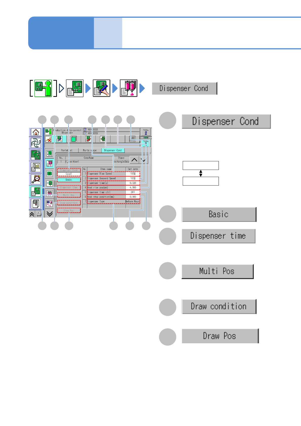
You can view and set the conditions of dispensing adhesives onto a PCB.
D
H
B
C
The dispensing timing condition setting
items are displayed. (Available when the
dispensing timing control is set “ON”)
E F
BC G I J
M L K
The basic condition setting items are displayed.
D
The setting items of the multipoint coordinate
data are displayed. (Available when there is
multipoint dummy dispensing data)
E
The setting items of drawing data are displayed.
(Available when there is drawing data)
F
The coordinates of the drawing data are
displayed.
(Available when there is drawing data)
The setting items of the conditions 1 and 2
are switched.
The conditions 1 and 2 are switched
depending on the order of the component
placement and dispensing.
If the data is not set, the condition is not
allowed to change.
Cond1
Cond2
Perform dispensing before
component placement
(standard)
Perform dispensing after
component placement
■[Dispensing condition] screen
NPM-W2 EJM7DE-MB-06O-00
6-1-15-2
I
J
K
L
M
G
H
100%
80%
60%
40%
20%
Dispenser Rise Speed
Dispenser Descend Speed
Dispensing time (s)
Head rise pos (mm)
Dispenser time ctrl
Whether the dispending timing is
controlled or not is displayed,
Head Stop Position (mm)
Dispenser type
The dispensing type is displayed.
The data cannot be modified on the
machine.
Choose the ascent velocity of a syringe.
Choose the decent velocity of a syringe.
The order for choosing the velocity is as
same as ‘Dispenser Rise Speed.’
The distance between PCB upper
surface and the nozzle lower end.
●Set value: 0.001 mm to 30.0 mm
Setting
change
NPM-W2 EJM7DE-MB-06O-00
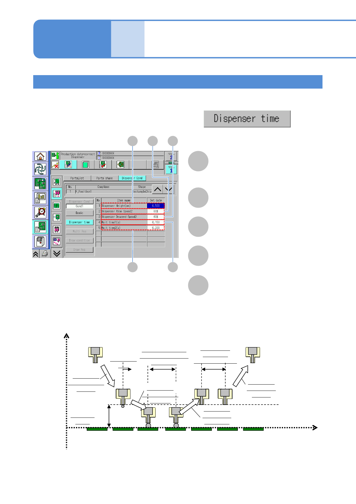
Setting the dispensing timing condition
From [Dispensing condition] screen (→ P.6-1-15-1)
Only when the dispensing timing control is set to[ON]
A B C
E D
A
Dispenser height (mm)
The distance from the nozzle tip to the
upper surface of the PCB where
dispensing is started is displayed.
B
Dispenser Rise Speed2
The dispensing rising speed (second
step) is displayed.
C
Dispenser Descend Speed2
The dispensing lowering speed (second
step) is displayed
D
Wait time1 (s)
The waiting time at the bottom dead
point in dispensing is displayed.
E
Wait time2 (s)
The waiting time after rising in
dispensing is displayed.
Z
Dispenser
height
Dispensing
lowering speed
1st step
Dispensing
start
Waiting time at the
bottom dead point in
dispensing
Dispensing
rising speed
2nd step b
Waiting time
after rising
During dispending
Dispensing
rising speed
1st step
Time
PCB top
surface
a
d
e
Dispensing
lowering speed
2nd step
c
Data
editing
Dispensing condition
data edit 2 (dispensing head)
Operating procedure
6-1-15
6-1-15-3