N7201A616E00_0317.pdf - 第706页
NPM-W 2 EJM7DE-MB-09O -00 9-1-10 -1 Specifi- cation Placement mode 1 Operating procedure 9-1-10 Feature ■ Alternate mode ● The head moves alternatively and performs production. ● Each head prod uces PCB on the front and …
NPM-W2 EJM7DE-MB-09O-00
9-1-9-4
At
a glance
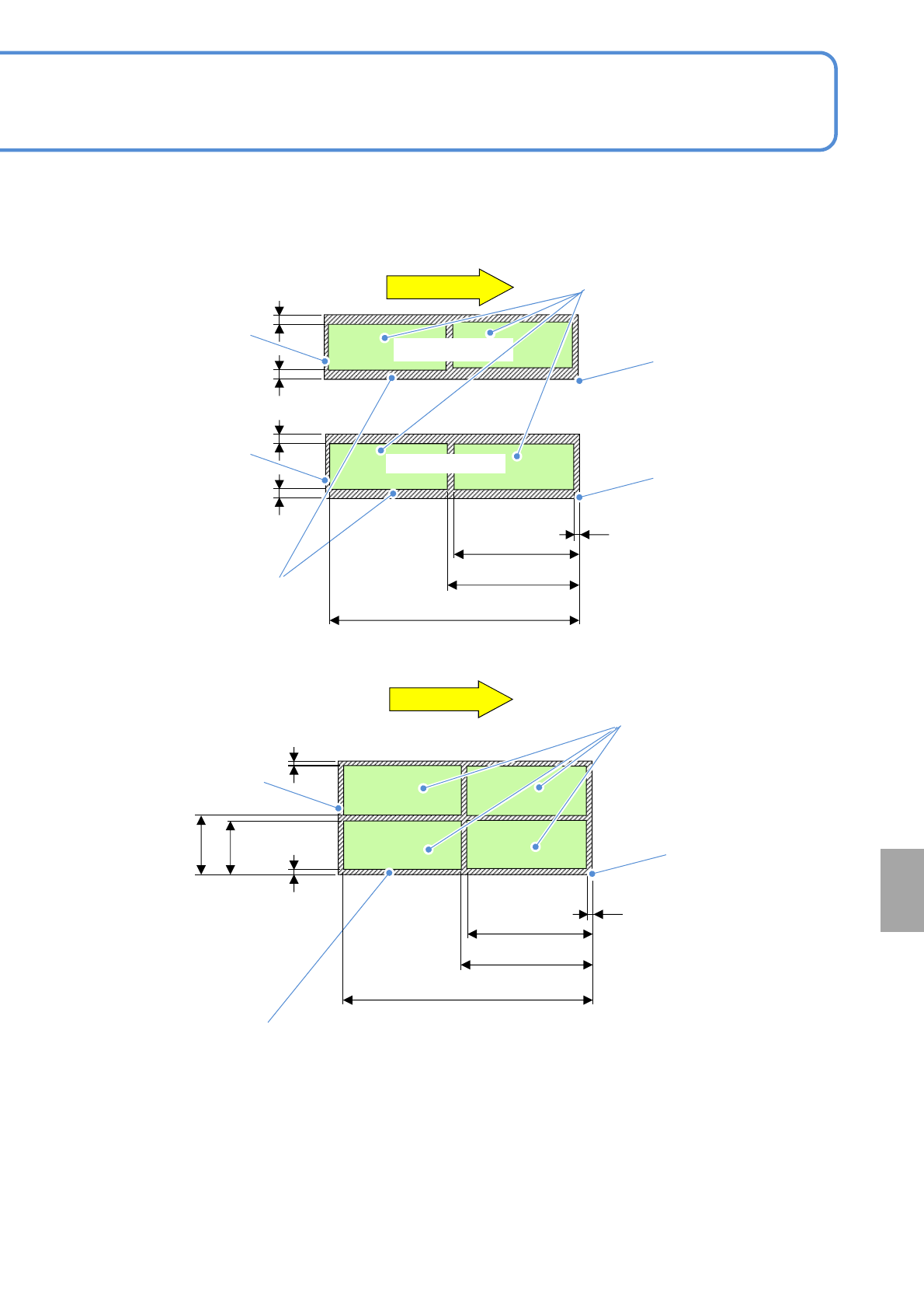
①Dual lane mode
■Dual conveyor (Unit: mm)
②Single lane mode
PCB flow
PCB flow
レーン2
more than
21
more than
21
more than 6
less than 344
less than 744
less than 406
less than
248.5
less than
268.5
PCB
outline
PCB
outline
Reference
Lane 2
Not arrangeable area
Arrangeable area
Lane 1
PCB
outline
Not arrangeable area
Arrangeable area
more than
21
more than
21
Reference
Reference
more than
21
more than
21
more than 6
less than 344
less than 744
less than 406
●The arrangement area drawing shows dimensions of the pin center arrangeable area based on PCB front
right reference.
(The same dimensions apply in the case of front left reference)
●The outline is not included in the arrangeable area.
●In single lane mode, support pins are arranged on the front head.
(If the placement head is attached only to the rear side, support pins are arranged on the rear head.)
●Because the support pins cannot cross over the PCB transport rail, the number of arrangeable pins on the
support block (home position) are varied depending on the PCB size and the number of pins to be used.
●The PCB flow direction on the drawing is from left to right. For right to left flow, dimensions will be
symmetrical.
NPM-W2 EJM7DE-MB-09O-00
9-1-10-1
Specifi-
cation
Placement mode 1
Operating procedure
9-1-10
Feature
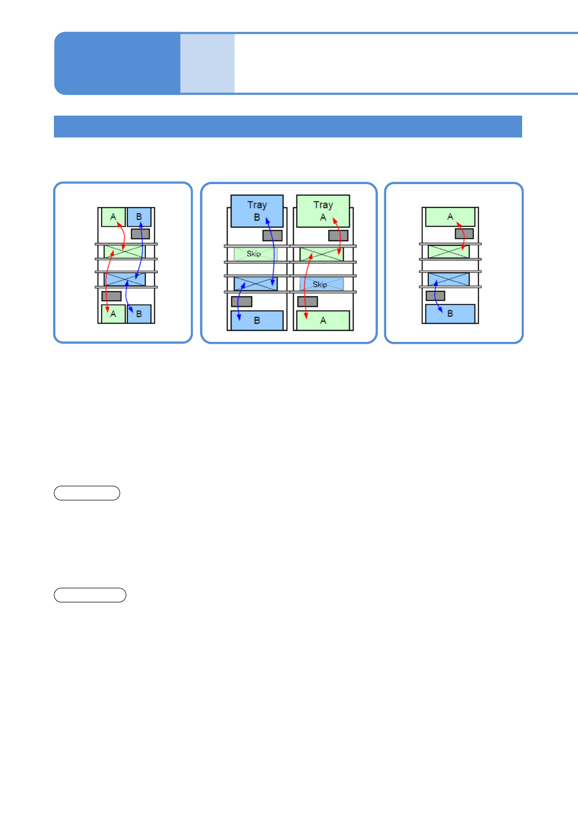
■Alternate mode
●The head moves
alternatively and performs
production.
●Each head produces PCB
on the front and rear lane.
●The head moves
alternatively and after
production of the target
lane completes, it
produces PCB on the other
lane.
■Alternate front (rear) mode
*1)
■Independent mode
*1)
●Using the front and rear heads,
only PCBs on the front (rear) lane
are produced, and PCBs on the
rear (front) lane are passed through.
●Each head independently
carries out production for
PCBs on each head.
Front head: Front lane
production
Rear head: Rear lane
production
●It minimizes the PCB
transfer loss.
●Production start and stop are
applicable per lane.
●Production start and stop
is applicable per lane.
●It improves productivity
because the head does not
need to wait for head
alternative motion (waiting
for motion of the other
head.
*2)
Changeover
●You need to stop the
machine to carry out
changeover for each lane.
●Changeover (changing the
production data or the feeder cart
*3)
,
or replacing the tray magazine) is
applicable for the suspended lane
while PCBs are passed through.
●Changeover (changing the
production data or replacing
the feeder cart
*3)
or the
tray magazine) is applicable
for the suspended lane
during one-side production.
*1)Independent mode and alternative (front / rear) mode are applicable for placement head specification.
*2)Head standby may arise depending on the PCB size.
*3) When changeover support unit is selected(→P.9-1-13)
Machine body
In dual lane mode, alternative mode and independent mode are available depending on the created data.
■Precautions
1. Any lane that the production data is not selected is not perform production.
2. Data creation and configuration of the placement mode are conducted on NPM-DGS.
For details, see the NPM-DGS instruction manual.
NPM-W2 EJM7DE-MB-09O-00
9-1-10-2
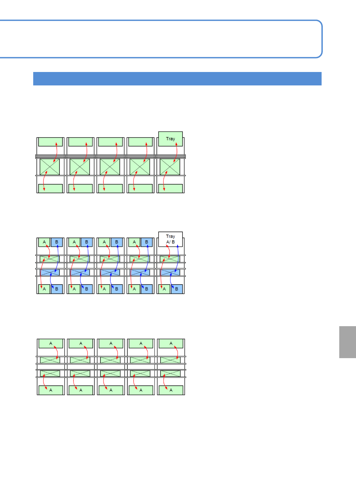
■Large size PCB mounting line
●Minimizes board transport losses.
●Realizes highly efficient production
through the smallest number of feeder
locations.
■High-efficiency mounting line
●Specifically designed for large size
boards that can not make use of dual
transport.
●Realizes the fastest placement of PCBs
of a pattern at the fastest rate.
The combination of placement modes allows NPM-W2 to respond to the needs of your various
production patterns.
Line
alternative mode
alternative mode (Single lane)
■Fastest mounting line
Independent mode
At
a glance