N7201A616E00_0317.pdf - 第399页
NPM-W 2 EJM7DE-MB-06O-0 0 6-1-13 -4 Setting change
NPM-W2 EJM7DE-MB-06O-00
6-1-13-3
A
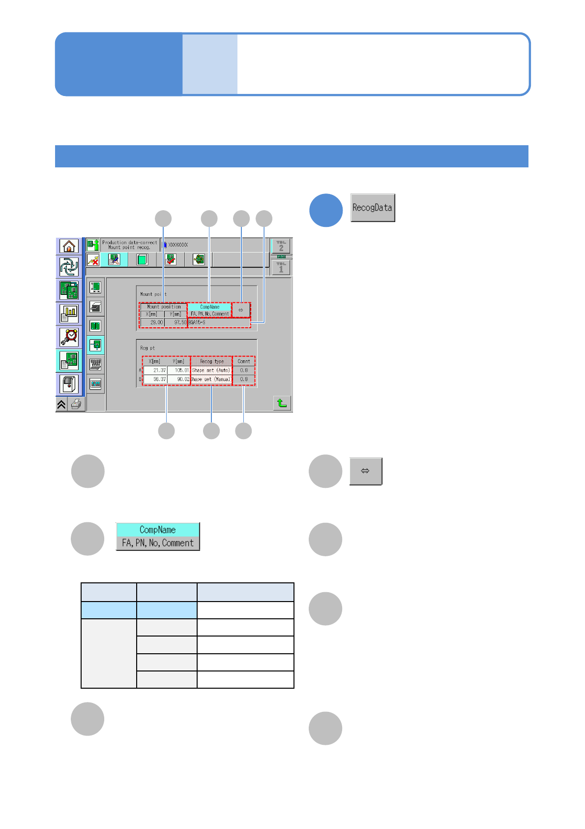
Mount position
E
X[mm]/Y[mm]
A B D
E F G
Recog type
F
Comment
G
C
B
CompName/FA, PN, No,
Comment
D
C
Shows the rest of component name if it
is too long to show the whole name.
XY coordinate of a placement point.
Coordinates of a recognition mark.
Recognition type of a recognition mark.
Pressing the [Type] field displays the
shape setting screen of each
recognition mark.
(→P.6-1-3)
Comment on a recognition mark set in DGS.
Displays the information of the selected
display type.
1
●Describes the screen on which to edit the placement points in production data.
Location Symbol Name
Upper field CompName Component name
Lower field FA Feeder address
PN Pattern No
No Sequence No
Comment Comment
Choose the display type.
Data
editing
Production data edit 2
Screen explanation 2
Operating procedure
6-1-13
●This button becomes enabled when
there is recognition data of placement
points.

NPM-W2 EJM7DE-MB-06O-00
6-1-13-4
Setting
change
NPM-W2 EJM7DE-MB-06O-00
6-1-13-5
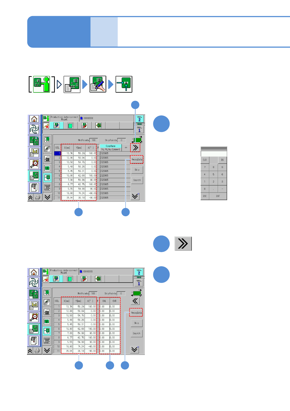
Describes how to confirm and edit production data.
2
1
Data
editing
Production data edit 3
Edit the data of the desired
field on the screen
●Touching the screen opens the
numerical input window (figure below).
1
■To set the length jutting from left or
right edge of a PCB
2
31
Edit the data of the desired
field on the screen
●Touching the screen opens the input
window.
3
4
4
Operating procedure
6-1-13