N7201A616E00_0317.pdf - 第683页
NPM-W 2 EJM7DE-MB-09O -00 9-1-5 -2 ● When you use the batch feed function in right and left lanes of the double tape feede r for the light weight 16-nozzle and the 12-nozzle hea d, software version of a double tape feede…
NPM-W2 EJM7DE-MB-09O-00
Specifi-
cation
Component/tray
specifications Intelligent
feeder specifications
9-1-5-1
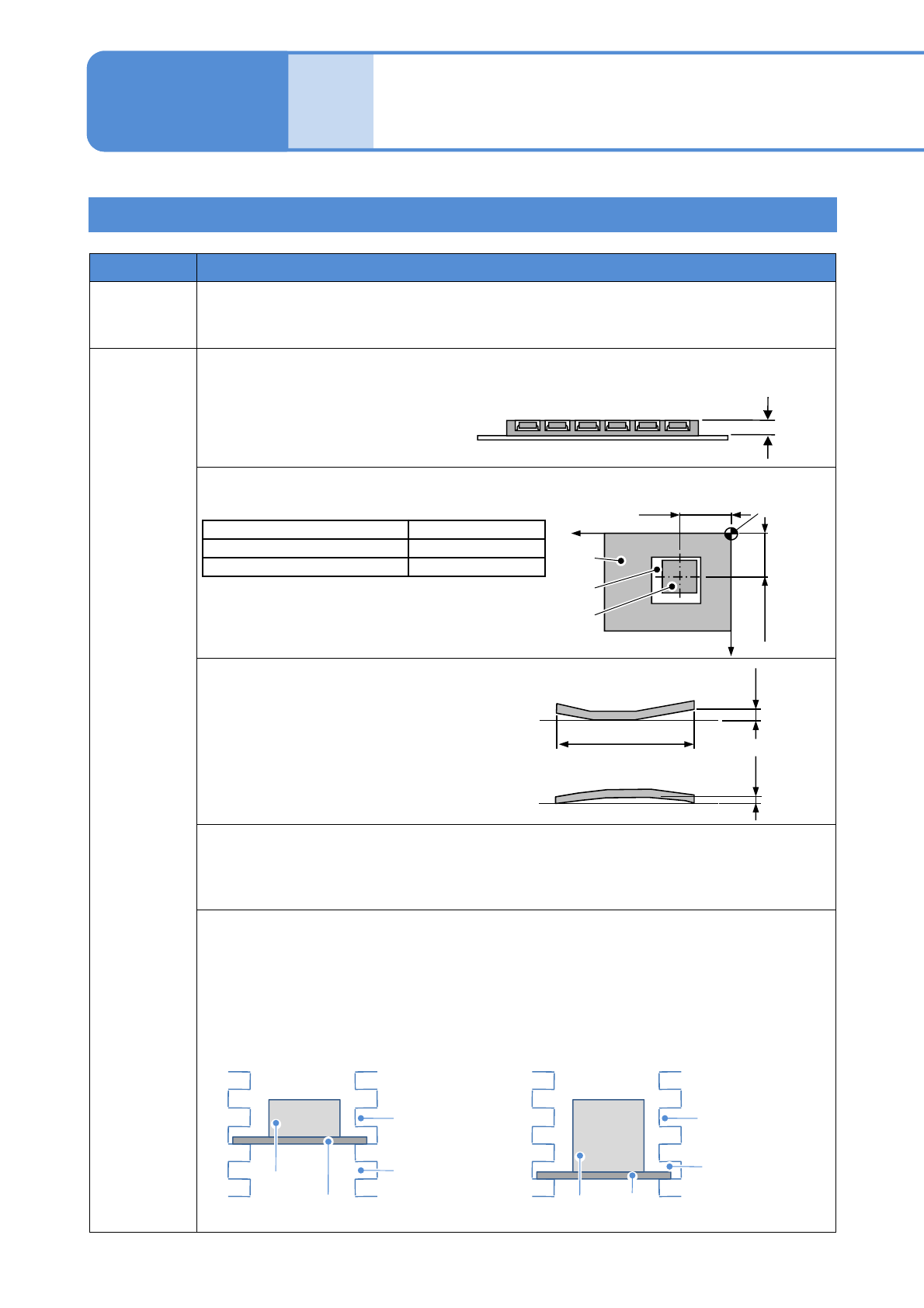
Item Specifications
Component
Dimensions: Max 100 90 mm (Diagonal side 134.5 mm)
Thickness: Max 30 mm
Mass: Max. 30 g
Tray
■Tray outside dimensions
●Max.
L 230 W 335 H33mm
●Min.
L 85 W 100 H2mm
■Relationship between component pickup surface and position error
●Top surface of component should be flat
■Warp (Clearance)
■Type
●For enough strength and dimensional accuracy, a tray should be injection-molded.
●Other than the above, we check your sample trays and suggest optional trays or
customization on costs.
■Loading the tray feeder pallet (option), the tray feeder magazine (option)
Condition
●Weight of a tray (including components) on a tray feeder pallet : 1 kg or less.
●Weight of a tray feeder magazine (including a tray feeder pallet, a tray, components) : 20
kg or less per magazine.
●Limitation of a tray feeder pallet insertion
・11 mm < tray height ≦ 26 mm ・26 mm ≦ tray height ≦ 33 mm
2to33mm
Component pickup surface Position error
10 10 mm or less 1.0 mm or less
10 10 mm or over 1.5 mm or less
Maximum 0.5 mm
Component tray
Tray
Tray
Max. 335 mm
Operating procedure
9-1-5
Clearance
Clearance
Tray
Not Insertable
at the top
Pallet
Magazine
Tray
Not insertable
at the top and
second level
Pallet
Magazine
Xw + Position error
Yw+Position
error
Tray setting
reference point
(Tray origin)
Tay
Component
X
Y
Pocket
NPM-W2 EJM7DE-MB-09O-00
9-1-5-2
● When you use the batch feed function in right and left lanes of the double tape feeder for the light weight
16-nozzle and the 12-nozzle head, software version of a double tape feeder must be 5.00 or later.
●The feeder for 4 mm tape width is custom specification. Please contact us.
NOTE
At
a glance
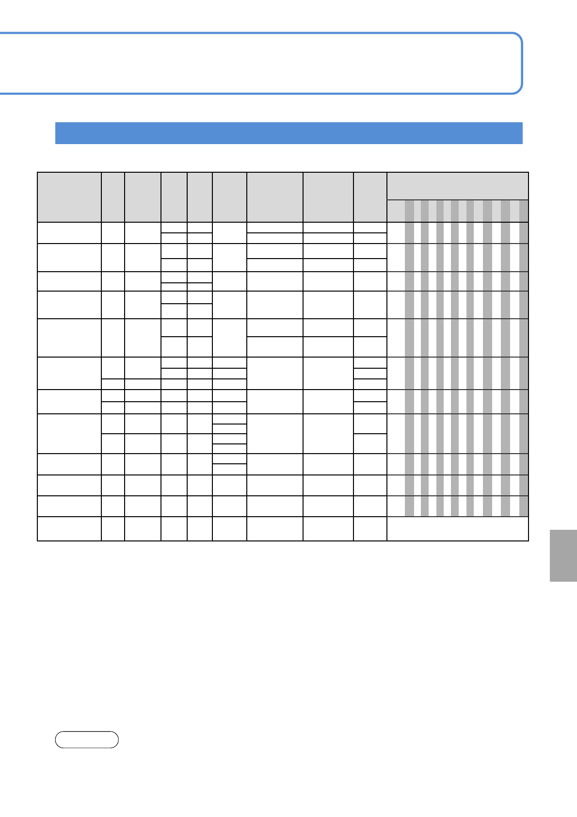
Intelligent feeder
Feeder type
Tape
width
(mm)
Type
Reel
diameter
*1)
Installa-
tion
pitch
(mm)
Max. depth
of boss
Max. inst. reel
count with a single
tray feeder
(option)
connected
*2)
Max. inst. reel
count with a
twin tray feeder
(option)
connected
*2)
Max.
installation
reel
count
*3)
Feed pitch (1 pitch = 4 mm)
0.250.51234567891011121314
8 mm
Double T/F
*4)
8
Paper
Embossed
Small 21
3
86 60 120
●
1mm
●●
Large 21 43 30 60
8 mm
Double T/F
*4)
(for 0402)
8
Paper
Embossed
Small 21
3
86 60 120
●●
Large 21 43 30 60
8 mm
Single T/F
8
Paper
Embossed
Small 21
343 3060
●
1mm
●●
Large 21
8 mm
Single T/F
(for 0402)
8
Paper
Embossed
Small 21
343 3060
●●
Large 21
8 mm
Thin type single
T/
F
*9)
(from 0402)
8
Paper
Embossed
Small 10.5
3
86 60 120
●
1mm
●●
Large 10.5 43 30 60
12 mm
16 mm
Shared T/F
12 Embossed
Small 21 15
43 30
60
●●●●
Large 21 15 60
16 Embossed Large 21 15
60
*5)
24 mm
32 mm
Shared T/F
24 Embossed
Large
42 15
21 15
30
●●●●●●●●
32 Embossed
Large
42 15 30
44 mm
56 mm
Shared T/F
44 Embossed
Large
63
15
14 10
20
●●●●●●●● ● ● ● ● ●
21
56 Embossed
Large
63
15
20
21
72 mm T/F
72 Embossed
Large
84
15
10 7 14
●●●●●●●● ● ● ● ● ●
21
88mm T/F
*6)
88 Embossed
Large
105 21 8 6 12
●●●●●●●● ● ● ● ● ●
104 mm
T/F
*6)
104 Embossed
Large
126 21 7 5 10
●●●●●●●● ● ● ● ● ●
32 mm
Adhesive T/F
*7) *8)
32 Adhesive
Large
63 2.8 14 10 20 3 (12 mm)
*1)
Small reel: φ178 mm, Large reel: φ 178 mm to φ382 mm
*2) This is the maximum number of reels to be installed when the tray feeder (option) is connected.
*3) This is the maximum number of reels to be installed when the feeder carts (option) are connected to
both of the two stages.
*4) Two small reels can be set.
Small and large reels cannot be set in the same slot of the reel container.
*5) Depending on the reel width, the maximum installation count may decrease.
*6) Only for a joint detection sensor equipped.
*7) No joint detection sensor equipped.
*8) An air supply unit (1 set/1 table) (option) is required.
*9) The thin type feeder can be used in NPM series and AM100.
When the thin type feeder is installed, “Attachment for thin type feeder” is required for each slot.
A small and large reels cannot be set in the same slot of the reel storage unit.
●Common to CM101, CM212, CM232, CM400 series, CM602, DT401, NPM series and AM100.
NPM-W2 EJM7DE-MB-09O-00
Nozzle specifications 1
Light weight 16-nozzle head
9-1-6-1
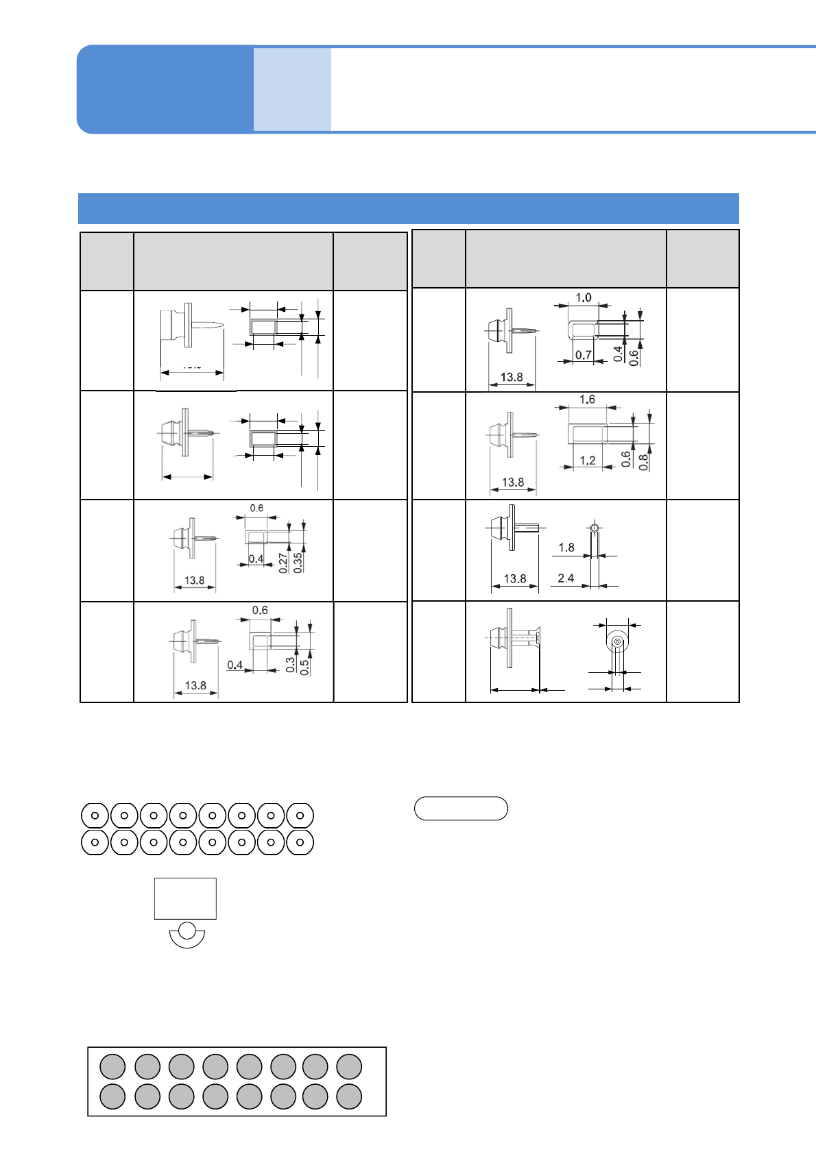
The machine is equipped with the standard nozzles in each head, supporting many different components.
Common to CM400 series.
Nozzle
No.
Shape (mm)
Target
componen
ts (Ex.)
230CS
230CSN
1005R, C
1608R, C
235CS
235CSN
1608R, C
2012R, C
3216R, C
SS-Mini Tr,
Di
S-Mini Tr, Di
240CS
240CSN
3216R, C
4532R, C
TAN-X
140S
140SN
AI electrolytic,
SOP
Nozzle
No.
Shape (mm)
Target
component
s (Ex.)
276S
276SN
*1)
03015R
256CS
256CSN
0402R, C
225CS
225CSN
0603R, C
226CS
226CSN
0603R, C
1005R, C
■Pickup component dimensions and
nozzle arrangement
(
●: Pickup enabled, ○: Pickup disabled)
●Pickup enabled component: 6 mm 6 mm or less
1 2 3 4 5 6
9 10 11 12 13 14
7 8
15 16
NOTE
Operating procedure
9-1-6
●For the nozzle No. including ‘C’, the nozzle tip is made of ceramic.
●For the nozzle No. including ‘N’, the 2D code is provided on the nozzle flange supporting the 2D code
recognition in the NPM series.
*1) Dedicated for the light-weight 16-nozzle
Specifi-
cation
13.8
0.3
0.2
0.1
0.24
13.8
4
0.2
1.5
2.5
Nozzle arrangement
Head
camera
123456
910111213
7
15
8
1614
(Condition seen from the top)
●The above 8 types come standard with the
nozzles for light weight 16-nozzle head; however,
the nozzles for 12-nozzle head (CM series) can
also be used.
●Light weight 16- / 16- / 12-nozzle heads are
compatible with one another.
The 03015 nozzles (276S/276SN) are used
exclusively for light weight 16-nozzle heads.
● The nozzles for 8-nozzle head and the AM100
nozzles cannot be used.
●In shadow recognition, the size and height of
components may be limited. (Because adjacent
nozzles are affected by the shadow cast by the
components)
0.39
0.32
0.17
0.3
13.8