N7201A616E00_0317.pdf - 第667页
NPM-W 2 EJM7DE-MB-09O -00 9-1-1 -10 At a glance Connector recognition condition (T ype 3 ) General con ditions of a connector whic h can be p laced are as follow s *1) . 8-nozzle head 3-nozzle head Outer dimensions 32 x …

NPM-W2 EJM7DE-MB-09O-00
Specifi-
cation
Operating procedure
9-1-1
9-1-1-9
Recognition unit configuration 3
BGA / CSP recognition condition (Type 3 )
Conditions of BGA / CSP which can be placed are as follows
*1)
.
8-nozzle head 3-nozzle head
Outer dimensions 2 x 2 to 32 x 32 mm 2 x 2 to 45 x 45 mm
Thickness 0.3 to 12 mm 0.3 to 30 mm
Minimum ball
pitch
0.5 mm 0.4 mm
Minimum ball
diameter
φ0.3 mm φ0.25 mm
Ball shape Ball
Ball material High temperature solder or eutectic solder
Number of balls 2 x 2 to 64 x 64 balls
Ball arrangement The balls should be uniform in pitch and size.
*2)
Supply type: Tape, tray
・Some ball surface conditions may prevent recognition.
・The supply type applies to those that have ball-shaped terminals on their under surface side.
・ Depending on the recognition speed or the number of leads, it may take a certain amount of time to wait
for recognition processing at the time of placement.
・ When the reflecting light is illuminated or the reflecting lamp offset value is set, the ball height inspection is
not performed.
*1) Basically, assess the availability of recognition by reviewing / conducting experimental placement using
samples.
*2) The same Ball Miss and Alternate pattern that are provided in the JEDEC and EIAJ with respect to BGA /
CSP are used.
●For details, contact us.
Machine specifications/
Basic performance 5
NPM-W2 EJM7DE-MB-09O-00
9-1-1-10
At
a glance
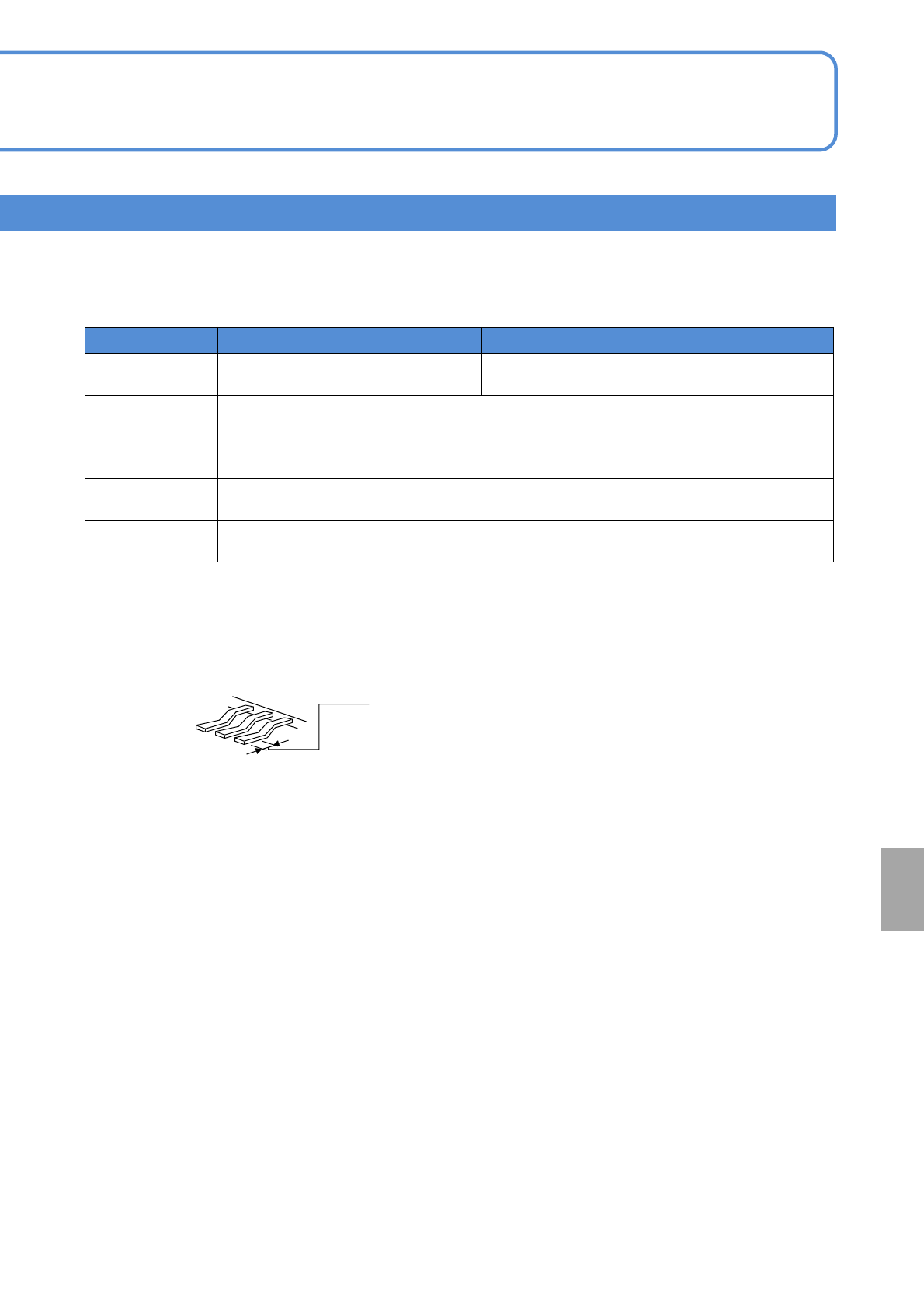
Connector recognition condition (Type 3 )
General conditions of a connector which can be placed are as follows
*1)
.
8-nozzle head
3-nozzle head
Outer dimensions 32 x 32 mm or less
L 100 x W 90 mm or less
*2)
Lead pitch 0.5 mm or more
Lead width 0.2 mm or more
Lead shape The amount of lead protrusion from the body should be 1 mm or more.
Other shape
There should be no through holes in a vertical direction around contact pins.
Contact pins should not be exposed on the under surface.
*1) Basically, assess the availability of recognition by reviewing / conducting experimental placement using
samples.
*2) In the case of placement of a large connector, its size may be limited due to a relationship between the
pickup position and the camera view as well as this condition.
●For details, contact us.
Supply type: Tape, tray, stick
・The measurement range of lead coplanarity is ±0.5 mm.
・ The planar portion of the lead under surface needs to be 0.2 mm or more in length
The planar portion of the under surface
0.2 mm or more
・Recognition may fail under certain under surface conditions of leads.
NPM-W2 EJM7DE-MB-09O-00
Specifi-
cation
Machine specifications/
Basic performance 6
Operating procedure
9-1-1
9-1-1-11
Recognition unit configuration 4
■Part thickness measurement function (Multi-recognition camera: [Type 2])
Improves placement quality through measurement of part thickness.
Item Description
Applicable
component
Each time 03015R
*1)
to Mini Tr / Di
Minimum part thickness: 0.1 mm
*To detect the pickup of a component being in a standing or slanted position, the difference
between any two of the following --- the thickness, width and length of the component ---
needs to be at least 50 μm.
Function
Part thickness
measurement
function
Each time
Part thickness is measured each time, which is
reflected in placement height. In addition, you can
simultaneously check the pickup of micro parts being
in a standing or slanted position and the reversing
pickup of Tr / Di.
Part teaching
You can make thickness measurement and chip data
entry on a per-part basis.
Nozzle top check
function
Checks the height of the nozzles for abnormalities.
*2)
Eject detection
function
If an error such as a recognition error has occurred, it checks the top of
the nozzles for any extraneous / foreign matter after ejecting parts.
・ This is not applicable to the measurement of nozzles with a pad or nozzles (e.g., 205A) the top of which is
dished.
・ Purchase on a per-table (front / rear) basis.
*1) When selecting “03015 placement support (option)”.
*2) Breaks, sliding failures in nozzle holders