N7201A616E00_0317.pdf - 第503页
NPM-W 2 EJM7DE-MB-06 O-00 6-2-10 -4 Setting change Confirm the recognition result ■ For OK PCB OK PCB ■ For defect PCB NG PCB + ● Choose the next bad mark. ● Displays in ‘Pattern’. 12 Confirm the message 13 + 13 (The r e…
NPM-W2 EJM7DE-MB-06O-00
Produc-
tion data
teaching
Bad mark recognition
teach 2
6-2-10-3
Operating procedure
6-2-10
5
5
5
6
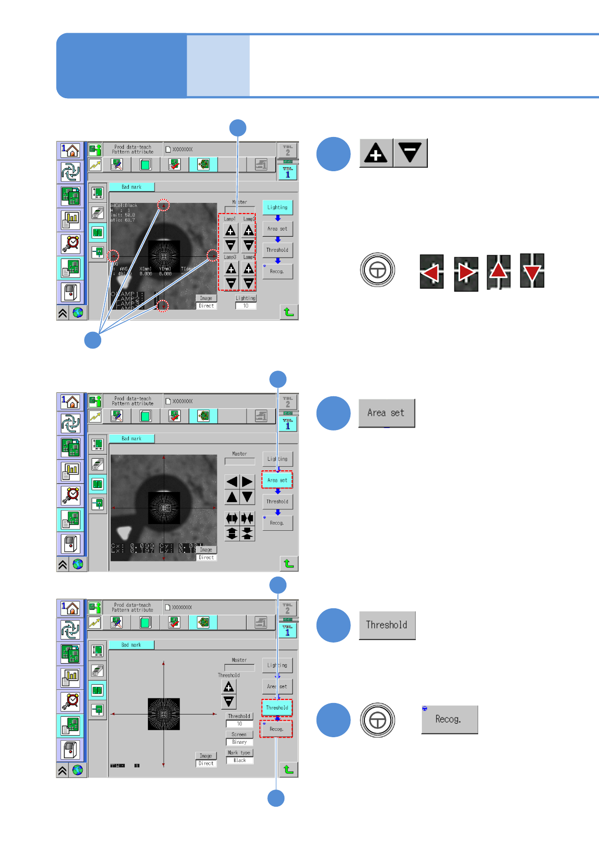
■When the position and the size of
recognition area are changed.
7
■When the threshold value being
recognized, screen switch or mark
type are changed.
6
8
7
+
8
After change
(Recognition is performed)
●Adjust the brightness to obtain the bad
mark. (→P.6-2-1 ‘How to adjust the
lamp value’)
■If the bad mark is not located
near the center
●Align the cross line center to the
bad mark center.
+
NPM-W2 EJM7DE-MB-06O-00
6-2-10-4
Setting
change
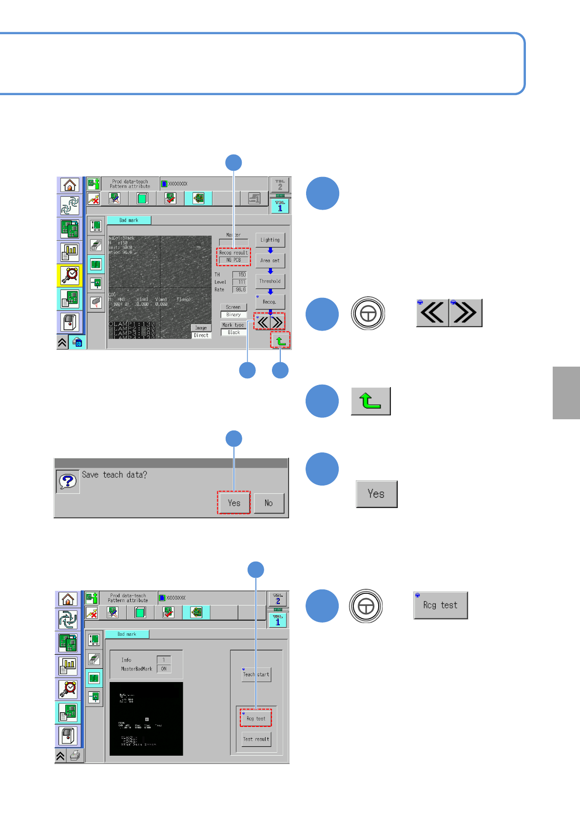
Confirm the recognition result
■For OK PCB
OK PCB
■For defect PCB
NG PCB
+
●Choose the next bad mark.
●Displays in ‘Pattern’.
12
Confirm the message
13
+
13
(The recognition result is displayed)
9
11
10
9
10 11
12
NPM-W2 EJM7DE-MB-06O-00
Produc-
tion data
teaching
Bad mark recognition
teach 3
6-2-10-5
Operating procedure
6-2-10
17
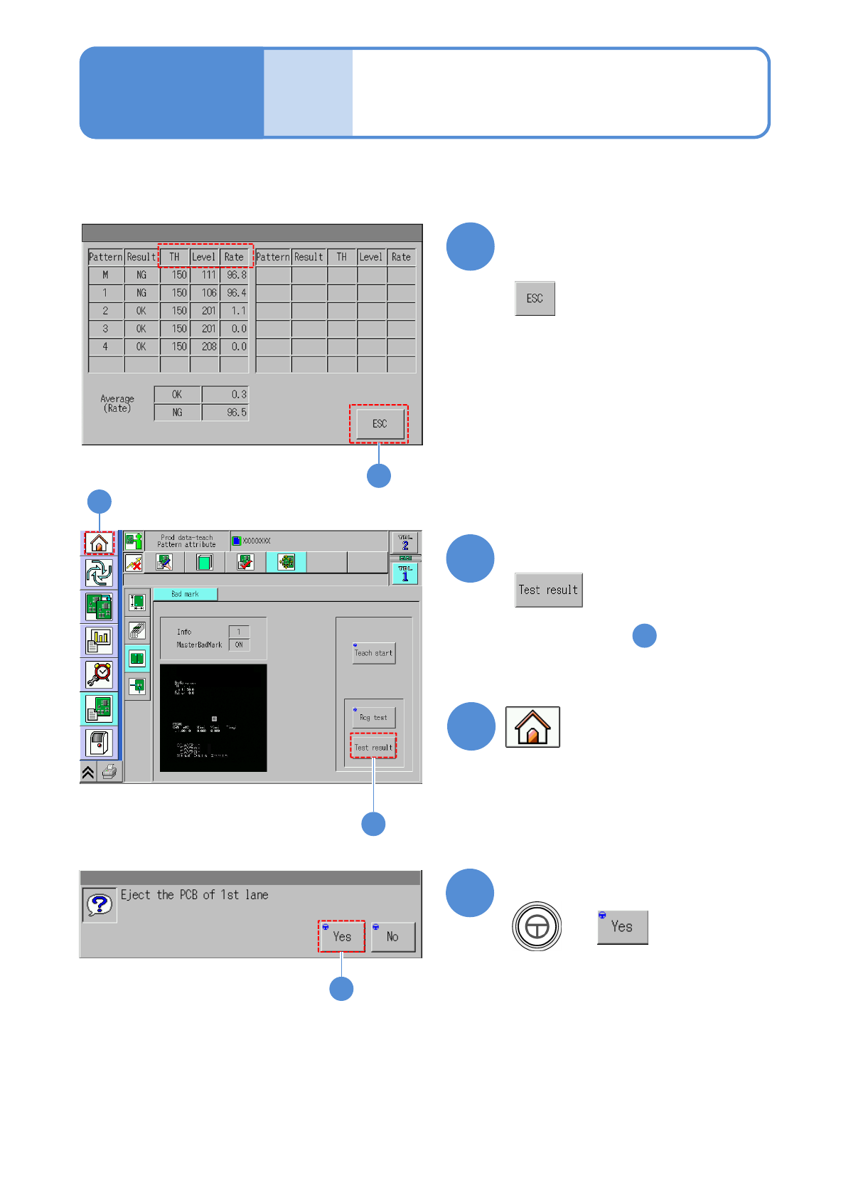
Confirm the message
15
To reconfirm the test result
(The test result of is displayed)
15
11
14
After confirming the
recognition result
16
●You may transition to the other
screen.
16
+
17
14
TH : Threshold
Level : Luminosity
Rate : Pixel rate