N7201A616E00_0317.pdf - 第317页
NPM-W 2 EJM7DE-MB-04 O-00 4-5-3 Component inspection Non-bar code scanner– based oper a tion Operating procedure 4-5-3 Defec- tive PCB process Only when such a communication switch as the one for bad ma rk recognition re…
NPM-W2 EJM7DE-MB-04O-00
4-5-2-6
Barcode scanner-
based operation 4
Operating procedure
4-5-2
Defec-
tive PCB
process
1
1
2
+
1
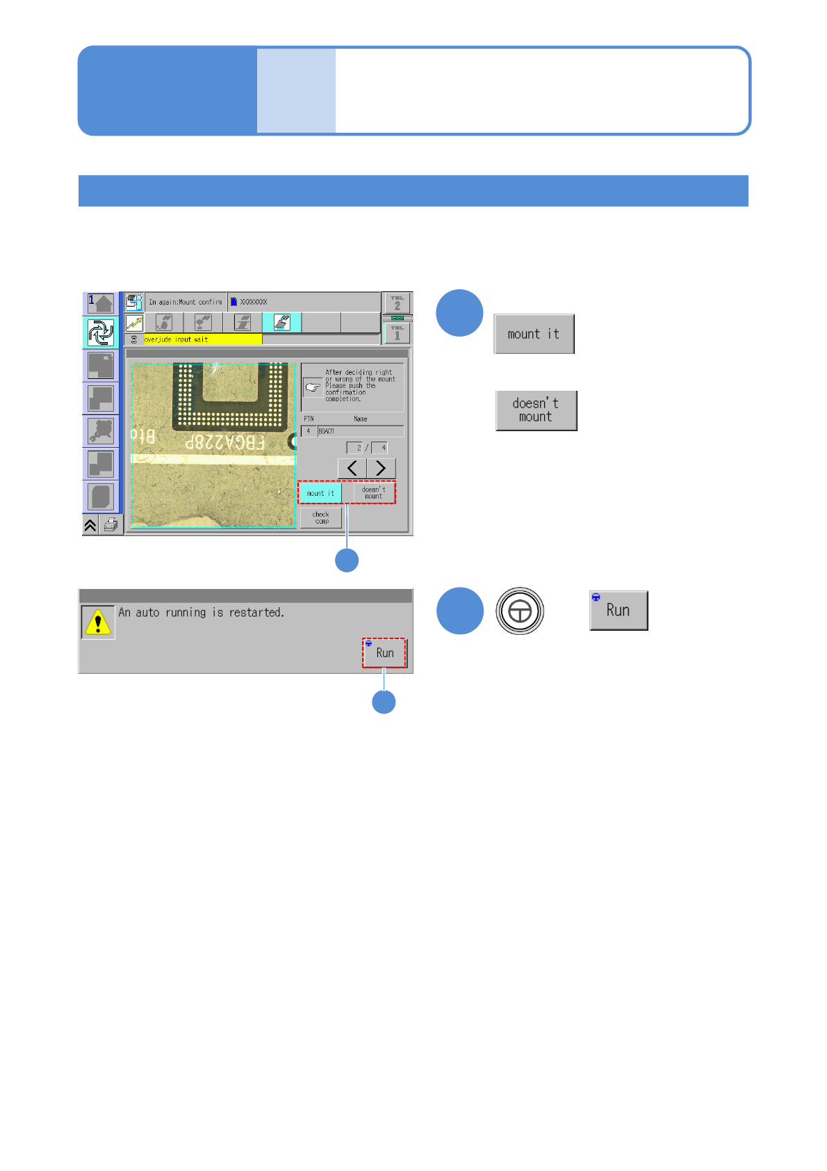
Component placement check during reloading
When the following confirmation screen appears during reloading, set whether components are placed or not
and continue the production.
(Automatic operation restarts)
■To place components
■Not to place components
NPM-W2 EJM7DE-MB-04O-00
4-5-3
Component
inspection
Non-barcode scanner–
based operation
Operating procedure
4-5-3
Defec-
tive PCB
process
Only when such a communication switch as the one for bad mark recognition results is
turned OFF and inter-machine communication of information such as the one related to
bad mark recognition results is not needed, reloading operation can be performed without
having to use the barcode scanner.
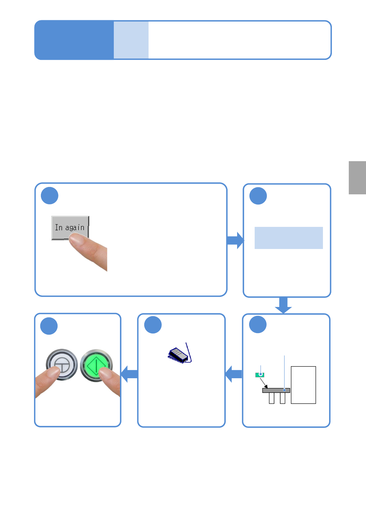
■Procedure for removing a defective PCB
Remove a PCB, which has been judged as defective, as is.
Repair the PCB in an appropriate manner, and store it temporarily so as to reload it.
1
●Unloading of PCBs on the
upstream side stops and the
machine comes to an immediate
(single) stop .
●When there is any PCB(s)
already loaded into the machine,
the machine comes to an
immediate stop after the PCB(s)
is unloaded from the machine.
3
Put the PCB on
the reload
conveyor
2
Confirm the
message
Reload conveyor
Repaired
PCB
『 Please put the
PCB.』
■Procedure for reloading a defective PCB
Operate as follows.
5
Start PCB
transportation
●Turn ON the
transportation restart
switch to start
transporting a PCB on
the reload conveyor.
Start production
ENABLING
START
4
NPM-W2 EJM7DE-MB-04O-00
4-6-1
A
B
C
D
E
Operation of the optional
display for NG map display
Operating procedure
4-6
●The optional display and a cable should be prepared on your own.
●It is connected to the MONITOR connector on the front of the inspection box.
([Maintenance] P.14-9)
Also the mouse is required. Please prepare it on your own.
●It is connected to the USB connector on the front of the inspection box.
([Maintenance] P.14-9)
●If the optional display for NG map display is placed on the inspection BOX, an operator may damage it by
hitting and knocking down with her/his body accidentally.
Secure the safety position such as beside the repair conveyor, and fix it not to fall.
●Never put anything, including the optional display for NG map display, on the inspection BOX.
Setting the soft switches
Turn ON the soft switch [Show NG map (monitor)] from [Setup of operation.]
(→P.4-2-1)
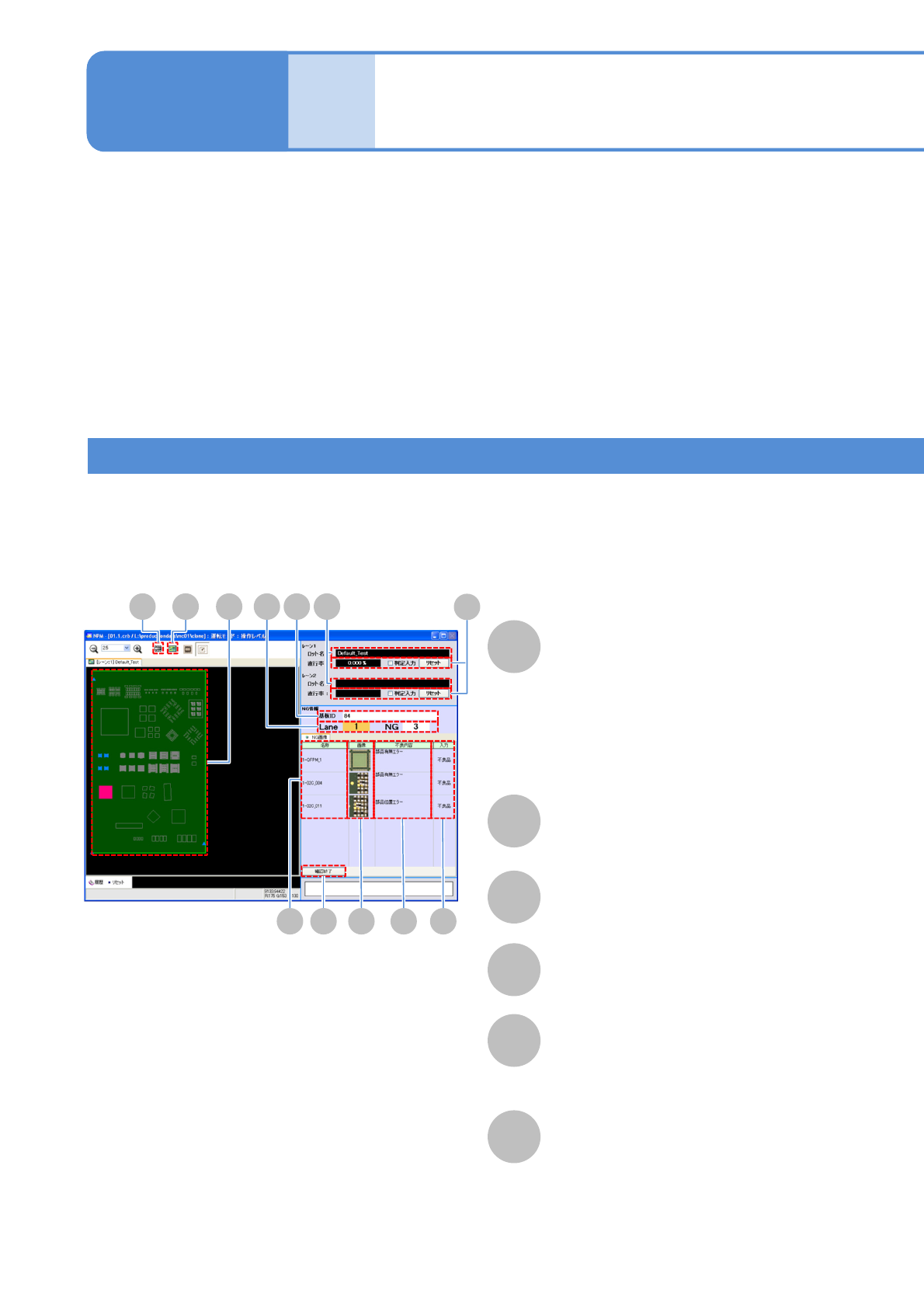
■Overall view of PCB
Lot name
NG map
PCB ID
Component name
NG image
A component is displayed in one of the
following colors, depending on the
inspection result.
●OK: Blue
●NG: Red
●Yet-to-be inspected: Gray
Displays NG image.
F
Defect
Displays an inspection item, regarding
which NG judgment has been formed.
D
H I BA
E F GJ
CK
L