N7201A616E00_0317.pdf - 第591页
NPM-W 2 EJM7DE-MB-07 O-00 (The support pin use nozzle will be attached to the head ) (The support pin use nozzle will be detached from the support pin use nozzle ch anger) 2 A 2 + + ■ To attach the nozzle ■ To detach the…
NPM-W2 EJM7DE-MB-07O-00
Unit
adjust-
ment
Operating procedure
7-2-5
Describes how to attach the nozzle for the support pin to the placement head after setting it to the nozzle
changer for the support pin.
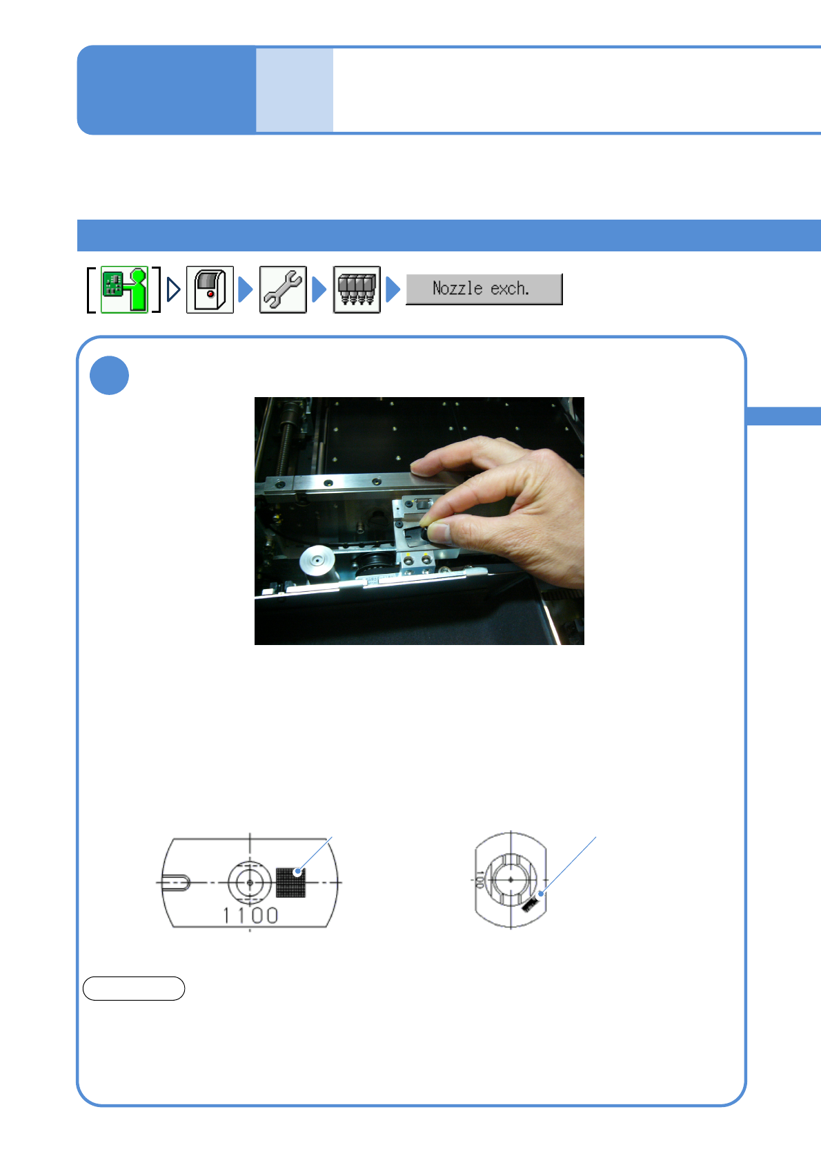
Attachment of the nozzle for the support pin
1
●Pay attention to the position of the
groove of the nozzle for the 3-
nozzle head.
Feeder table side
●Set the nozzle for the light weight 16-, 12-, or 8-nozzle head,
positioning it as shown below.
●The option setting can be used to read 2D codes and detect
nozzle types so as to prevent the wrong nozzle from being set.
Feeder table side
100-nozzle
(for light weight 16-, 12-, 8-nozzle head)
1100-nozzle
(for 3-nozzle head)
2D code
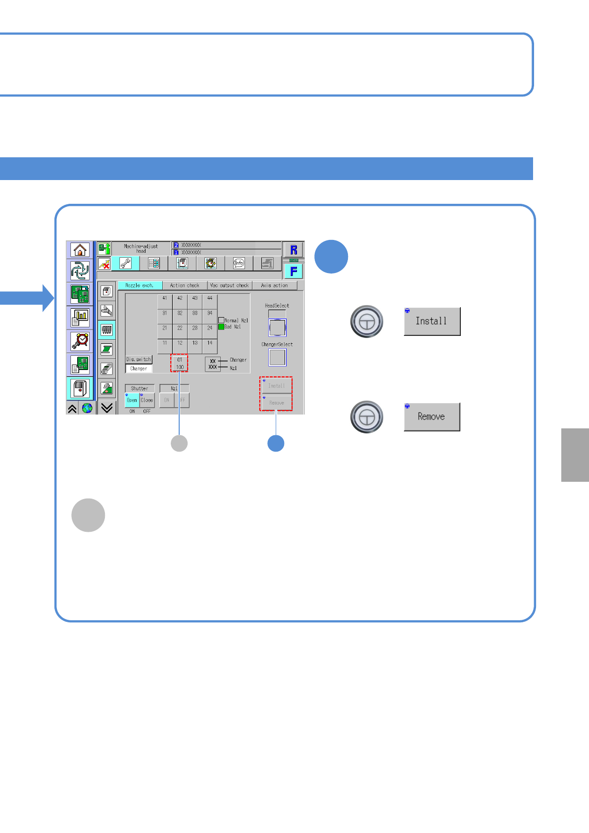
Set the nozzle intended for support pin use to the nozzle changer
intended for support pin use
2D code
Support pin use nozzles
ATTENSION
The support pin use nozzles differ in shape from the ones specifically used for picking up
components.
Make sure to attach the support pin use nozzle to the support pin use nozzle changer and, the
component pickup use nozzle, to the component pickup use nozzle changer.
Attachment of a wrong nozzle may damage the shaft of the head unit.
7-2-5-5
Replacing the nozzle of
the placement head 3
NPM-W2 EJM7DE-MB-07O-00
(The support pin use nozzle will be
attached to the head)
(The support pin use nozzle will be
detached from the support pin use
nozzle changer)
2A
2
+
+
■To attach the nozzle
■To detach the nozzle
A
Support pin use nozzle changer
Displayed when automatic change function
specifications are selected for the support
pin. When attaching/detaching the support
pin use nozzle, you will select it.
7-2-5-6
Attachment/detachment of
the nozzle
System
administration
NPM-W2 EJM7DE-MB-07O-00
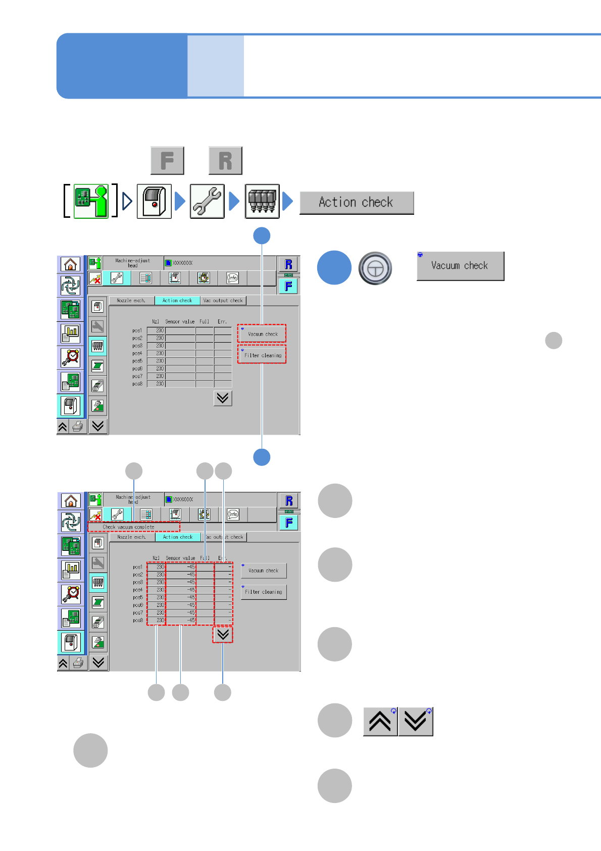
■If vacuum check has completed successfully
[Check vacuum complete] is displayed in .
■If vacuum check failed to complete
successfully
The background of the measured value of the
corresponding nozzle is displayed in yellow.
Unit
adjust-
ment
Action check of the
placement head
7-2-6-1
You can collectively check whether the actions of the placement head or nozzles are normal.
●Perform on both and .
Operating procedure
7-2-6
1
+
A B
C D
A
B
C
F
E
F
2
1
D
E
F
(The vacuum check result of each nozzle
is displayed)
Nozzle
A number of a nozzle attached to the
placement head.
●”-” is displayed if any nozzle is not
attached.
Sensor value
●If the measured value is abnormal, its
background is shown in yellow.
Full
●Filter clogging detection value. Check
if the measured value is abnormal as
the result of [Filter cleaning].
The previous or next table
is displayed.
Err.
●Nozzle clogging detection value.
Check if the measured value is
abnormal as the result of [Vacuum
check].
Message display area