N7201A616E00_0317.pdf - 第625页
NPM-W 2 EJM7DE-MB-07 O-00 Machine parame- ter Operating procedure 7-3-13 7-3-13 A A F our points of fset ch e ck (inspection head) You can check the offset value (calibration result) when the inspectio n head moves to th…
NPM-W2 EJM7DE-MB-07O-00
Machine
parame-
ter
Operating procedure
7-3-12
7-3-12
A
B
C
A
B C
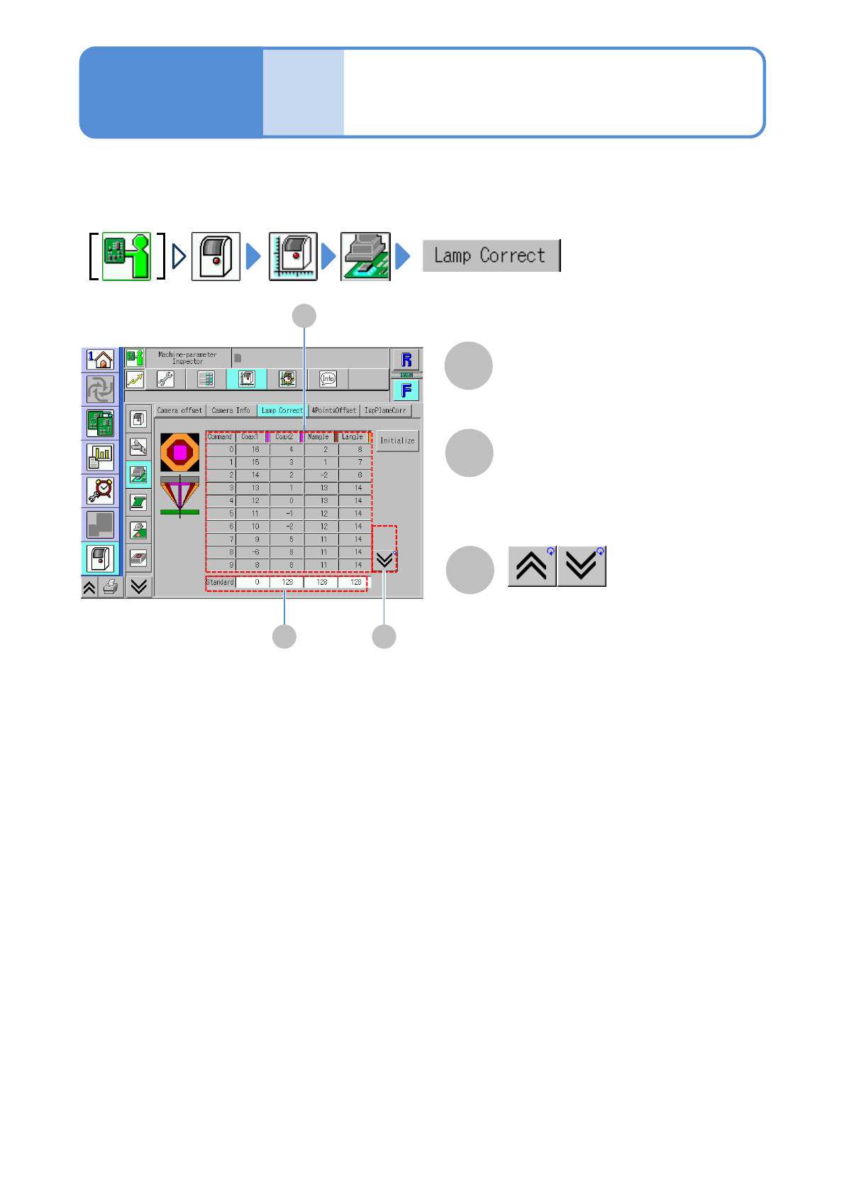
Lamp value offset
check (inspection head)
You can check the offset value (calibration result) of the inspection head light unit.
Lamp offset value
Displays a previous or next table.
Standard light value
■For component inspection
0 / 128 /128 /128
■For solder inspection
30 / 0 / 0 / 200
NPM-W2 EJM7DE-MB-07O-00
Machine
parame-
ter
Operating procedure
7-3-13
7-3-13
A
A
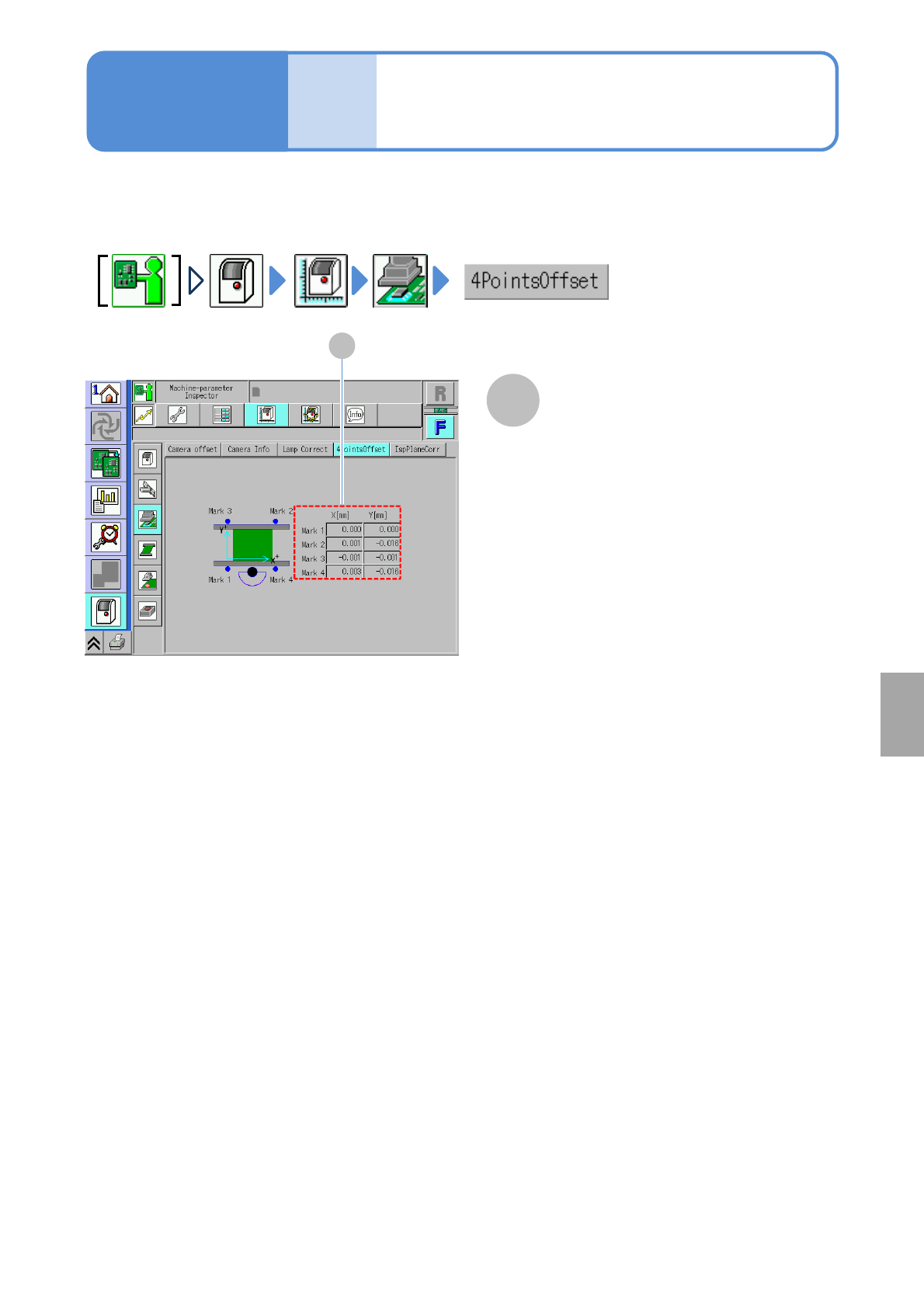
Four points offset
check (inspection head)
You can check the offset value (calibration result) when the inspection head moves to the XY standard mark
position.
●For dual conveyor, choose a lane 1 in advance. (For how to switch the lane(→P.2-2-1-9 ‘Lane switch button’))
Standard mark coordinates
X[mm]/Y[mm]
Offset values of the inspection head on
XY coordinates of a transport conveyor
standard mark.
System
administration
NPM-W2 EJM7DE-MB-07O-00
Machine
parame-
ter
Operating procedure
7-3-14
7-3-14
A
C
B
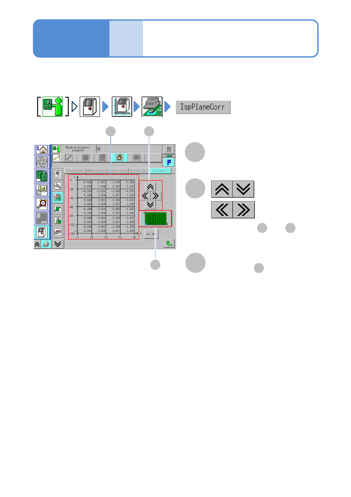
Inspection plane offset
check (inspection head)
You can check the offset value (calibration result) of the bonding side used when the inspection head
corrects the PCB recognition position and placement position.
A
Offset
Offset values of the bonding side
●Displays every 20 mm interval.
B
C
:Vertical direction
:Horizontal direction
●Displays area and .
A C
Area display
●Displays area in blue color.
A