00196625-03_AI_SX12_PCB_Barcode_de_en.pdf - 第107页
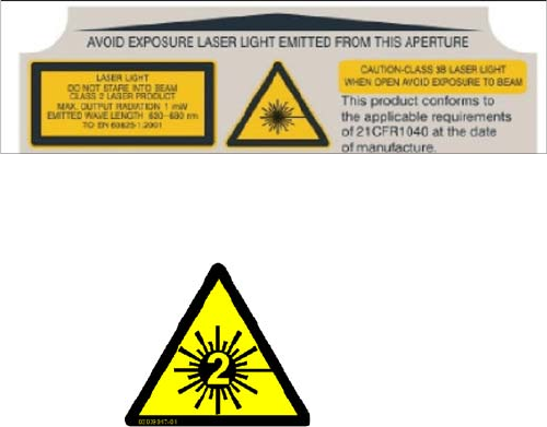
Introduction Warning Labels Safety Instructions PCB Barcode LP-Barcode 107 1.1.4 Warning Labels 1.1.4.1 Laser Note on the 1D PCB Barcode Scanner Warning labels on the rear s ide of the 1D PCB barcode scanner The lase r n…
Introduction
Safety Instructions Safety Instructions for the Power Supply
106 PCB Barcode LP-Barcode
1.1.2 Safety Instructions for the Power Supply
▪ This means that some parts of the system carry potentially lethal voltages - even when switched off
at the main power switch.
▪ Incorrect handling of the placement system can therefore result in fatal injuries, severe injuries or
considerable damage to equipment.
▪ Measurements and maintenance work must always be carried out by appropriately qualified person-
nel.
▪ Always follow the applicable accident prevention and DIN regulations (particularly DIN EN 60 204,
part 1) or the regulations specific to your country.
▪ Before starting any maintenance work, switch off at the main switch and disconnect the machine
from the main power supply.
▪ Always secure the machine against unauthorized reactivation. If these instructions are not followed,
you may be able to touch live parts, which could result in fatal or severe injuries.
Maintaining or replacing assemblies
► End all placement operations on the machine.
► Shut down the Windows operating system correctly, otherwise problems may occur when restarting
or data may be lost.
► Switch the machine off at the main switch.
► Disconnect the machine from the main power supply.
► Switch off the machine and attach warnings signs to indicate that service work is in progress.
1.1.3 Safety Instructions for the Gantry
WARNING
Hazardous Voltages!
The machine is supplied with 3 x 400 V~ (or 3 x 204 V~ / 3 x 230 V~ / 3 x 380 V~ / 3 x 415 V~)
± 5 %, 50/60 Hz mains voltage.
► Observe the safety instructions in the user manual during all service work!
CAUTION
Moving the gantry can damage the placement head.
When moving the gantry, observe the following:
► NEVER move the gantry by pushing with your hands against the placement head.
► NEVER push the gantry while the Z axis is lowered.
Introduction
Warning Labels Safety Instructions
PCB Barcode LP-Barcode 107
1.1.4 Warning Labels
1.1.4.1 Laser Note on the 1D PCB Barcode Scanner
Warning labels on the rear side of the 1D PCB barcode
scanner
The laser note is located on the rear side of the 1D PCB
barcode scanner.
LASER RADIATION!
Do not look into beam
Laser class 2
Item No. 03009347-01
Introduction
Preparatory Work... Warning Labels
108 PCB Barcode LP-Barcode
1.2 Preparatory Work...
Purpose and scope
Before performing any preventive maintenance work or service work, a procedure of locking and tagging
must be followed and warning signs must be attached. The procedure, when followed correctly, elimi-
nates the possibility of an employee being injured.
Description
Whenever it becomes necessary to isolate, control and release energy, the following procedure is to be
followed.
► Notify affected employees.
► Switch off the machine and all additional devices. Carry out all normal stopping procedures:
⇨ Press the STOP button.
⇨ Shut down the station computer.
⇨ Switch the machine off at the main switch.
► Isolate the machine from all its energy sources:
⇨ Shut off the compressed air supply.
⇨ Shut off the main power supply.
► Lock out the machine.
⇨ Attach a lock wherever possible (e.g. to the main power switch or the motor contactor).
NOTICE
Additional safety measures
These procedures represent the minimum lock/tag out requirements for the machine during
preventive maintenance work and service work. Any additional safeguards needed to complete
work safely can be specified by facilities supervision, the safety officer, the safety committee
and the health department.
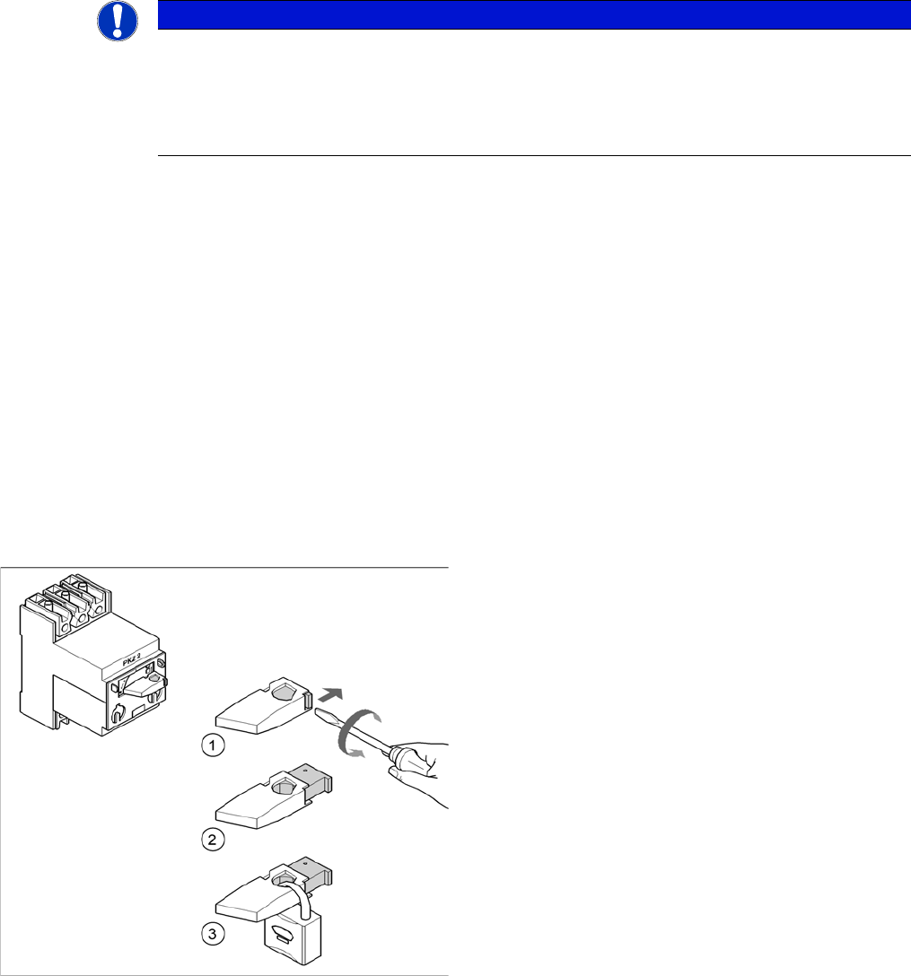
Example: attaching a padlock to the motor contactor
► Turn the operating lever (1) counterclockwise.
► Use the screwdriver to push the locking lug (2) out of
the operating lever (1).
► Secure the operating lever with a padlock (3).