00196625-03_AI_SX12_PCB_Barcode_de_en.pdf - 第194页
Setting up and Commissioning Removing the PCB Barcode Adjusting the Machine Configuration in the Station Software. 194 PCB Barcode LP-Barcode
Setting up and Commissioning
Adjusting the Machine Configuration in the Station Software. Removing the PCB Barcode
PCB Barcode LP-Barcode 193
3.4 Removing the PCB Barcode
You can remove the PCB barcode scanner in its holder from the mounting frame inside the machine.
This may be necessary, for example, if the scanner beam angle or scanning direction needs to be ad-
justed or if a defective scanner needs to be replaced.
► Take the pointer out of its holder.
► Use the lever on the relevant holder to loosen the fixtures from the mounting frame.
► Unplug the SUB-D connector.
► Remove the holder from the machine.
► Perform the following tasks. See "3.2 Installing the PCB Barcode Scanner" [ ➙ 121].
► Plug the SUB-D connector back in.
► Reinsert the holder into the mounting frame.
► Reinsert the pointer into the holder.
► Redetermine the Y position. Refer to "3.3.1.2.2 Configuring the Barcode Scanner Software" [➙ 168]
for 1D PCB barcode scanners and "3.3.2.1.2 Configuring the Barcode Scanner Software" [ ➙ 178]
for 2D barcode scanners.
Converting to another barcode scanner type
If you need to convert from 1D to 2D barcode scanners or vice versa, you need to remove the complete
mounting frame, corresponding wiring and the scanner from the machine.
Continue to fit the new scanner. See "3.2 Installing the PCB Barcode Scanner" [ ➙ 121].
WARNING
Cables may only be connected to or disconnected from the machine when currentless.
The connector encoding informs the conveyor control that a scanner is to be used at the rele-
vant installation position. If the scanner is missing, an error message will be issued.
► Please note that scanner cables may only be connected to the option board if the corre-
sponding scanner has been fitted.
► Take care that the cables do not get into the hazard area of the machine.
CAUTION
Make sure that you use the correct set of cables. Never mix up the cable sets for 1D and 2D
scanners. When using a 1D barcode scanner, you must fit the intermediate adapter (gender
changer).
Setting up and Commissioning
Removing the PCB Barcode Adjusting the Machine Configuration in the Station Software.
194 PCB Barcode LP-Barcode
Annex
Technical Data - 1D PCB Barcode Scanner
PCB Barcode LP-Barcode 195
4 Annex
4.1 Technical Data - 1D PCB Barcode Scanner
Technical data.
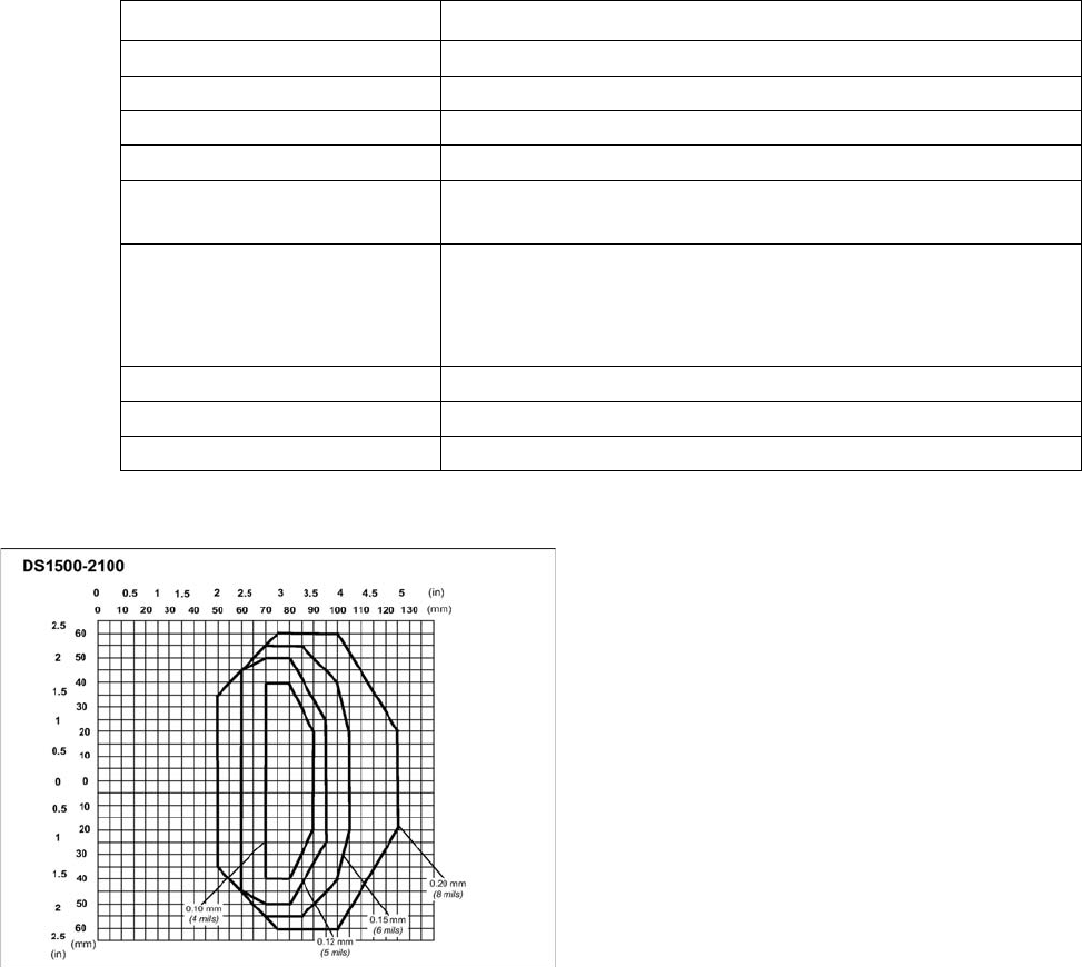
Scan field diagram
Dimensions (L x W x H)
40 x 30 x 20 mm
3
Weight 44 grams
Wave length 600 to 680 nm
Laser class Class 2, in line with DIN EN 60825-1, class II - CDRH
Scanning frequency 800 to 1200 scans/second
Code types Code 39, Code 128, Code 93, Codabar, EAN, EAN 128, UPC, 2/
5 Interleaved, Pharma Code, ISTB 128
Barcode length
single conveyor
dual conveyor, asynchronous
dual conveyor, synchronous
max. 40 characters
max. 40 characters
max. 40 characters
Data interface RS232, RS485
Electrical connection 15-pin D-Sub HD connector
Operating voltage 5 V- ± 5 %
Scan field diagram of 1D PCB barcode scanner
(0/0) is the centerpoint of the laser beam output window.
Prerequisites
Code = Interleaved 2/5 or Code 39
PCS = 0.90
"Pitch" angle = 0°
"Skew" angle = 15°
"Tilt" angle = 0°
Motor control = speed_3 (800 scans/s)
This parameter can be set in WinHost.