00196625-03_AI_SX12_PCB_Barcode_de_en.pdf - 第122页
Setting up and Commissioning Installing the PCB Barcode Scanner Installation Position in the Holder 122 PCB Barcode LP-Barcode 3.2.1 Installation Po sition in the Holder The various installation positio ns for 1D and 2D …
Setting up and Commissioning
Use and Arrangement
PCB Barcode LP-Barcode 121
3 Setting up and Commissioning
3.1 Use and Arrangement
The barcode scanners are installed in a mounting frame which is fitted to the outside of the machine base
on the input side of the board conveyor.
Up to two PCB barcode scanners can be retrofitted onto single conveyors. These can then scan in the
top and bottom of the boards.
Up to four PCB barcode scanners can be retrofitted to dual conveyors. These can then scan in the top
and bottom of boards on both conveyor lanes.
3.2 Installing the PCB Barcode Scanner
Each PCB barcode scanner is fitted into a mounting frame, which is attached to the docking unit.
The following options for installation in the mounting frame are available for the 1D barcode scanner:
▪ At cross angles to the direction of travel "3.2.2.2 Installing the 1D PCB Barcode Scanner at Cross
Angles to the Direction of Travel" [ ➙ 124]
▪ Parallel to the direction of travel, left"3.2.2.3.1 Parallel to the Direction of Travel, Left" [ ➙ 125]
▪ Parallel to the direction of travel, right"3.2.2.3.2 Parallel to the Direction of Travel, Right" [ ➙ 128]
The following options for installation in the mounting frame are available for the 2D barcode scanner:
▪ Parallel to the direction of travel, left"3.2.3.3.1 Parallel to the Direction of Travel, Left" [ ➙ 132]
▪ Parallel to the direction of travel, right"3.2.3.3.2 Parallel to the Direction of Travel, Right" [ ➙ 135]
The choice of installation position depends on the position of the barcode on the board and on any in-
terfering edges on the board. In principle, we recommend that the barcode scanner is fitted to the side
opposite the barcode.
NOTICE
Different conveyor versions
The procedure is alike at the different conveyor versions in principle. Any differences will be ex-
plicitly indicated.
CAUTION
Pay attention to the conveyor version
► The pointer version used will depend on the conveyor.
Use the long pointer [03073262-xx] at V1-conveyors.
Use the short pointer [03095905-xx] at V2-conveyors.
► The position of the ruler is represented by the example of a V1-conveyor.
At V2-conveyors the position of the ruler differs from the pictures.
► See also"3.2.8 Fitting the Ruler" [ ➙ 158]
NOTICE
Combination of various scanner types not possible
1D and 2D scanners can not be combined in one and the same machine.
Setting up and Commissioning
Installing the PCB Barcode Scanner Installation Position in the Holder
122 PCB Barcode LP-Barcode
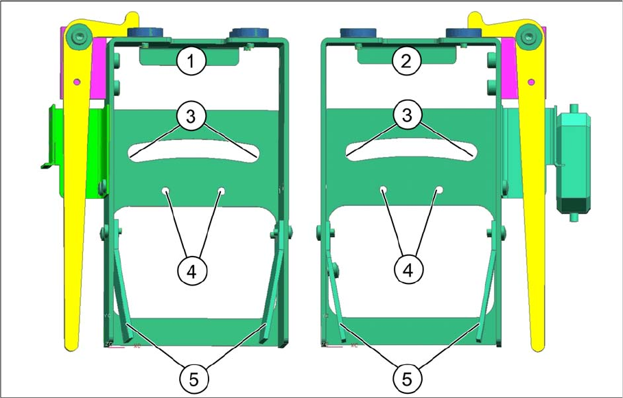
3.2.1 Installation Position in the Holder
The various installation positions for 1D and 2D PCB barcode scanners are realized in the holder, as
shown in the diagram.
Legend
1 Holder for BC scanner, mirrored
[03078730-xx]
2 Holder for BC scanner [03077716-xx]
3 Arched aperture with mounting position for fix-
ing bracket and clamping piece, BC scanner
right / left
4 Mounting position for BC scanner, cross an-
gles (1D only)
5 Park positions for unused BC holding brackets
Setting up and Commissioning
Installing the 1D PCB Barcode Scanner Installing the PCB Barcode Scanner
PCB Barcode LP-Barcode 123
3.2.2 Installing the 1D PCB Barcode Scanner
3.2.2.1 Fixing the 1D PCB Barcode Scanner to the Bracket
The following holding rackets are supplied:
▪ 1D BC holding bracket right and left [03084154-xx]
▪ 2D BC holding bracket left [03083915-xx]
▪ 2D BC holding bracket right [03084153-xx]
The 1D PCB barcode scanner is already preinstalled on its cover angle. For the 1D PCB barcode scan-
ner, use the 1D BC bracket, right and left [03084154-xx].
Unused holding brackets are fixed into the holder to ensure that are not lost (see position 5 in "3.2.1 In-
stallation Position in the Holder" [ ➙ 122]).
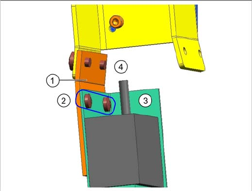
Fixing barcode scanner to bracket
Legend
1. 1D BC holding bracket right and left [03084154-xx]
2. Screws DIN 7985-M3 x 3-A2-Z [00368583-xx]
3. Barcode scanner with cover angle
4. Drilled holes for fixture to fixing bracket or holder
► Fix the barcode scanner with its cover angle (3) to the
bracket (1) with the help of the two screws (2).
The installation position on the bracket is the same for all
barcode scanner fitting options.
When installing the barcode scanner parallel to the direc-
tion of travel, the holding bracket must be screwed to the
fixing bracket in the position shown at (4) (see "3.2.2.3.1
Parallel to the Direction of Travel, Left" [ ➙ 125] and
"3.2.2.3.2 Parallel to the Direction of Travel, Right" [ ➙
128]).
When installing the barcode scanner at cross angles to
the direction of travel, the holding bracket is screwed di-
rectly to the holder in the position shown at (4) (see
"3.2.2.2 Installing the 1D PCB Barcode Scanner at Cross
Angles to the Direction of Travel" [ ➙ 124]).